
Utility Valve Station & Valve Cluster
A utility valve station (or valve cluster) is a pre-engineered, factory-assembled, pressure-tested compact assembly providing all the valves, instruments, and connection points required to isolate, control, measure, and protect a defined steam or condensate service point — typically comprising isolation valves, a PRV set, a safety valve, a steam trap with bypass, a pressure gauge, a thermometer, and a check valve, all mounted on a common SS 316L or carbon steel base frame or panel. A valve cluster multiplies this concept with 4–24 individual service outlets on a shared manifold, each independently isolatable and metered.
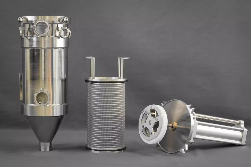
A utility valve station (or valve cluster) is a pre-engineered, factory-assembled, pressure-tested compact assembly providing all the valves, instruments, and connection points required to isolate, control, measure, and protect a defined steam or condensate service point — typically comprising isolation valves, a PRV set, a safety valve, a steam trap with bypass, a pressure gauge, a thermometer, and a check valve, all mounted on a common SS 316L or carbon steel base frame or panel. A valve cluster multiplies this concept with 4–24 individual service outlets on a shared manifold, each independently isolatable and metered.
Steam enters the valve station through the main inlet isolation valve; passes through the separator and strainer to remove condensate and particles; enters the PRV which reduces pressure to the set process pressure; exits through the outlet isolation valve to the process user. A safety valve on the downstream side provides overpressure protection in case of PRV failure. The steam trap set (with upstream/downstream isolation and bypass) drains condensate from the station body and associated pipework. A pressure gauge and temperature gauge confirm correct operating conditions. All components are connected in a defined arrangement on a compact skid — factory-tested before installation.
Challenges
PRV Failure to Control Causing Downstream Overpressure
Pilot or seat failure in PRV allows full upstream pressure to reach process user — process equipment overpressure.
Condensate Backup in Valve Station from Failed or Blocked Steam Trap
Trap blockage or failure allows condensate to accumulate in the station body — steam quality deteriorates; water hammer risk.
Safety Valve Chattering from Back-Pressure in Discharge Line
Excessive back-pressure on safety valve outlet prevents full opening — reduces rated relief capacity; causes valve chatter.
Access Difficulty for Maintenance on Compact Multi-Valve Clusters
Closely spaced valves on compact cluster panel restrict wrench access — maintenance time extended; safety risks in confined space.
Instrument Calibration Drift on In-Line Pressure Gauges Over Time
Bourdon tube gauges drift ±5% over 2–3 years in vibrating environments — operators trust inaccurate readings.
Solutions
- Downstream Safety Valve Sized for Full PRV Capacity (1.1× PRV Maximum Flow): Safety valve sized for full upstream flow — provides complete overpressure protection even if PRV fails fully open.
- Dedicated Trap Station with 3-Valve Set (Inlet Isolate, Outlet Isolate, Bypass): All traps installed with upstream/downstream isolation and bypass valves — maintainable live without station shutdown.
- Safety Valve Discharge to Safe Location Via Dedicated Blowdown Pipe (Vertical, Unobstructed): Dedicated discharge pipe to safe outdoor location — prevents back-pressure and directs discharge away from personnel.
- Maintainability Clearance: Minimum 600 mm Access Width Around Cluster Panel: Design specification for 600 mm minimum clearance on all four sides — safe ergonomic maintenance access.
- Digital Pressure Transmitter (4–20 mA, ±0.1% Accuracy) Replacing Bourdon Gauge on Critical Services: Smart transmitter replaces Bourdon gauge — remote monitoring, no calibration drift, alarm integration to SCADA.
Applications
- Pharmaceutical (GMP Suite): Clean steam station at every autoclave, SIP line, and CIP heat exchanger — pre-tested, documented, IQ/OQ/PQ ready.
- Food & Beverage: Culinary steam stations at cooking vessels, pasteurisers, and CIP heat exchangers — culinary steam certification.
- Chemical Processing: Process steam station at each reactor, reboiler, and heat exchanger — pre-engineered, delivered to site ready to connect.
- Hospital / Healthcare: Steam station at each steriliser and CSSD unit — with safety valve, pressure gauge, and maintenance bypass.
- Industrial: Multi-service valve cluster in mechanical services room supplying heating, process steam, and condensate to plant rooms.
Table A — Single-Service Utility Valve Station: Models & Capacities
Single-Service Utility Valve Station — Models & Capacities (DN 15 to DN 100) | |||||||||||
Model | Steam Service DN [mm] | Max Inlet Pressure [bar(g)] | PRV Set Pressure Range | Steam Capacity (max) [kg/h] | Safety Valve Set Pressure [bar(g)] | Trap Type Included | Instruments Included | Skid L×W×H [mm] | Skid Material | Pressure Test [bar] |
|
UVS-015-7 | DN 15 | 7 | 0.3–5 bar adj. | 60 | 5.5 | F&T DN 15 | P-gauge, T-gauge | 400×200×400 | SS 316L | 10.5 |
|
UVS-015-16 | DN 15 | 16 | 0.3–10 bar adj. | 100 | 10.5 | F&T DN 15 | P-gauge, T-gauge, P-switch | 450×220×450 | SS 316L | 24 |
|
UVS-025-7 | DN 25 | 7 | 0.3–5 bar adj. | 350 | 5.5 | F&T DN 20 | P-gauge, T-gauge | 550×280×550 | SS 316L / CS | 10.5 |
|
UVS-025-16 | DN 25 | 16 | 0.3–10 bar adj. | 500 | 10.5 | F&T DN 20 | P-gauge, T-gauge, P-transmitter | 600×300×600 | SS 316L / CS | 24 |
|
UVS-040-16 | DN 40 | 16 | 0.5–10 bar adj. | 1,500 | 10.5 | F&T DN 25 | P-gauge, T-gauge, P-transmitter, flow | 750×380×700 | CS galv. | 24 |
|
UVS-050-16 | DN 50 | 16 | 0.5–10 bar adj. | 3,000 | 10.5 | F&T DN 32 | P-gauge, T-gauge, 2× P-transmitter, flow | 900×450×800 | CS galv. | 24 |
|
UVS-080-16 | DN 80 | 16 | 1–10 bar adj. | 8,000 | 10.5 | F&T DN 40 | Full instrumentation + SCADA | 1,200×550×1,000 | CS galv. | 24 |
|
UVS-100-16 | DN 100 | 16 | 1–10 bar adj. | 18,000 | 10.5 | Disc DN 50 | Full instrumentation + SCADA | 1,500×650×1,100 | CS galv. | 24 |
|
Table B — Multi-Outlet Valve Cluster: Models & Capacities
Multi-Outlet Valve Cluster — Models & Capacities (2 to 12 Outlets) | |||||||||||
Model | Header DN [mm] | Outlet Count | Outlet DN [mm] | Max Inlet Pressure [bar(g)] | Total Steam Capacity [kg/h] | PRV per Outlet | Trap per Outlet | Instruments per Outlet | Panel L×W×H [mm] | Panel Material |
|
VCL-02-25 | DN 50 | 2 | DN 25 | 16 | 1,000 | Yes (DA PRV) | Yes (F&T) | P-gauge + T-gauge | 600×150×800 | SS 316L |
|
VCL-04-25 | DN 80 | 4 | DN 25 | 16 | 2,000 | Yes | Yes (F&T) | P-gauge + T-gauge | 900×150×1,000 | SS 316L / CS |
|
VCL-06-25 | DN 100 | 6 | DN 25 | 16 | 3,000 | Yes | Yes (F&T) | P-gauge + T-gauge | 1,200×200×1,000 | CS galv. |
|
VCL-06-40 | DN 100 | 6 | DN 40 | 16 | 7,500 | Yes | Yes (F&T) | P-gauge + T-gauge + P-switch | 1,400×200×1,100 | CS galv. |
|
VCL-08-40 | DN 150 | 8 | DN 40 | 16 | 10,000 | Yes | Yes (F&T) | Full per outlet | 1,800×250×1,200 | CS galv. |
|
VCL-12-40 | DN 200 | 12 | DN 40 | 16 | 15,000 | Yes | Yes (F&T) | Full per outlet | 2,400×250×1,300 | CS galv. |
|
VCL-12-50 | DN 200 | 12 | DN 50 | 16 | 30,000 | Yes (PO PRV) | Yes (disc) | Full + P-transmitter | 2,600×300×1,400 | CS galv. |
|