
PBT Agitator (Pitched Blade Turbine)
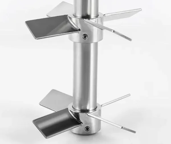
A pitched blade turbine is a versatile axial-radial flow impeller with blades angled at 30–45 degrees to the horizontal. Generating combined axial and radial flow, it is used for blending, solid suspension, heat transfer, and gas-liquid mixing across a wide range of process scales. It is one of the most widely used impeller types in pharmaceutical, chemical, food, and bioprocess manufacturing.
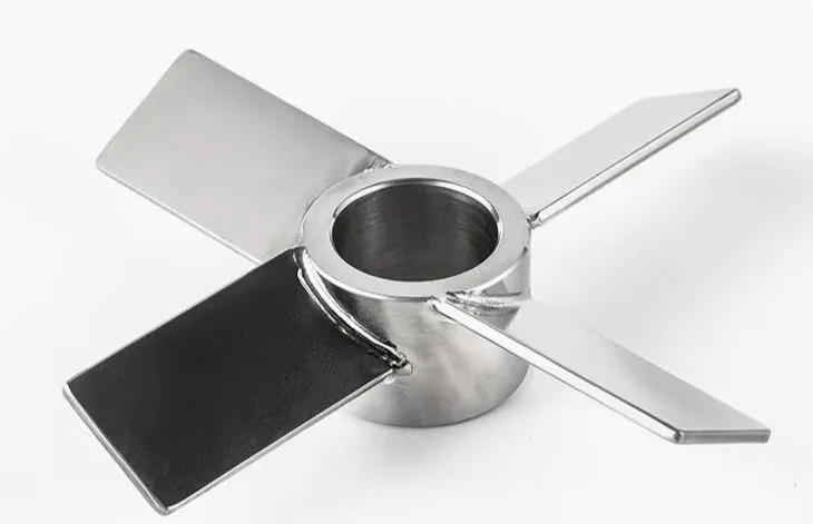
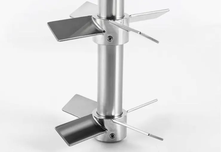
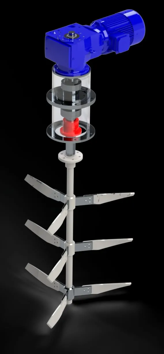
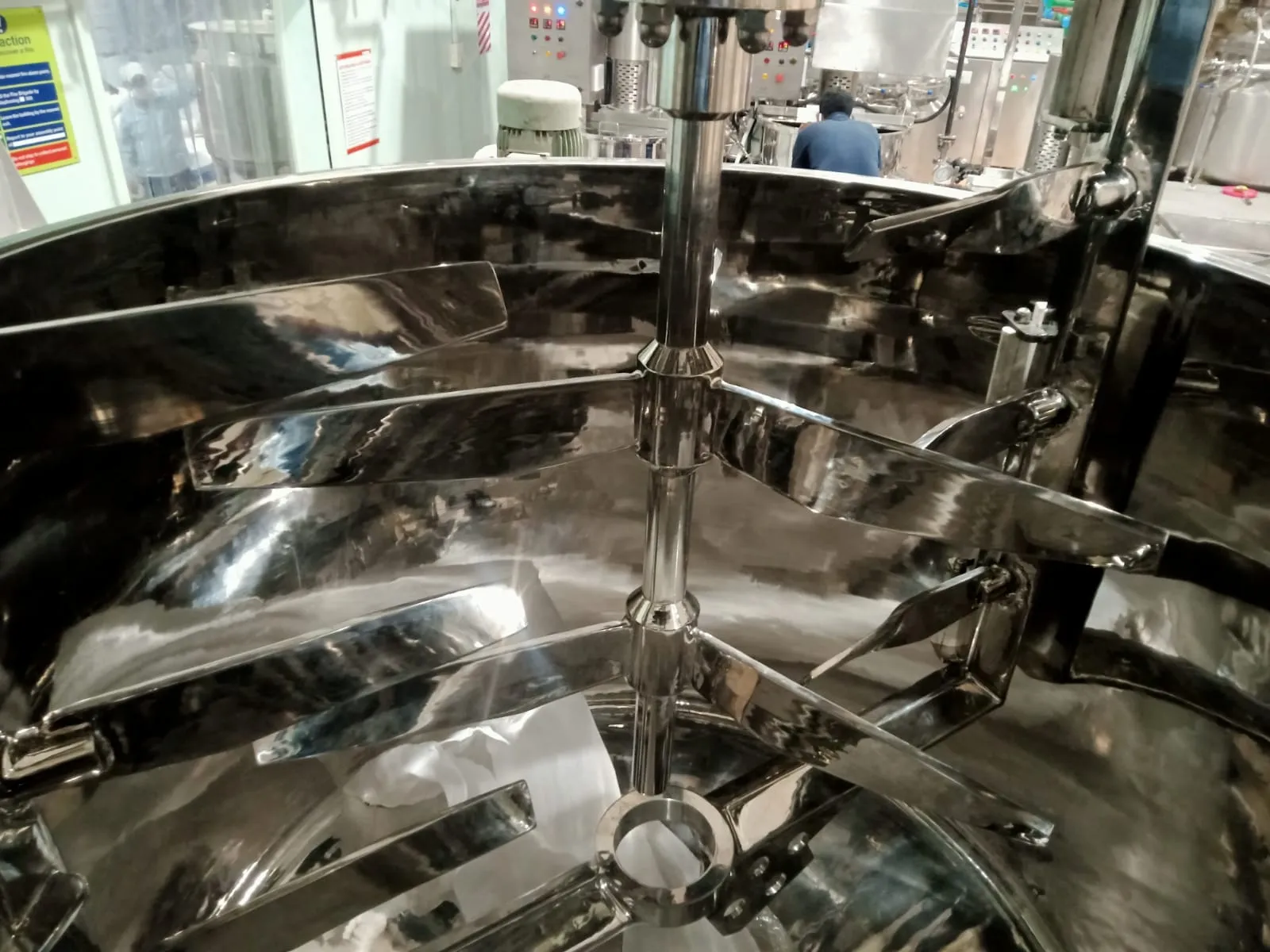
A pitched blade turbine is a versatile axial-radial flow impeller with blades angled at 30–45 degrees to the horizontal. Generating combined axial and radial flow, it is used for blending, solid suspension, heat transfer, and gas-liquid mixing across a wide range of process scales. It is one of the most widely used impeller types in pharmaceutical, chemical, food, and bioprocess manufacturing.
The angled blades generate a downward axial flow component combined with radial discharge at the impeller plane, creating top-to-bottom circulation loops throughout the vessel. This combined flow pattern maintains solids in suspension, promotes heat transfer at the vessel wall, and distributes gas bubbles when sparging is used. Multiple impellers stacked on a single shaft extend coverage in tall vessels with high height-to-diameter ratios.
Challenges
Insufficient Shear for Fine Emulsification and Hard Agglomerate Dispersion
The moderate tip speed and shear generated by a pitched blade turbine are inadequate for producing fine droplet emulsions below approximately 20–50 µm or for breaking down hard crystalline agglomerates, requiring a higher-shear impeller type for these duties.
Vortex Formation at Higher Speeds Without Baffles
Operating without baffles at higher rotational speeds induces solid body rotation and a surface vortex, drawing air into the batch and reducing mixing effectiveness by replacing productive axial flow with unproductive circular motion.
Stratification in Tall Vessels with Single Impeller
In vessels with a height-to-diameter ratio above approximately 1.2 to 1.5, a single pitched blade turbine cannot generate sufficient axial circulation to prevent concentration and temperature stratification in regions far from the impeller.
Increased Power Demand in Transitional Reynolds Number Range
In the transitional flow regime between laminar and fully turbulent, the power number of the pitched blade turbine rises, increasing power consumption per unit volume and making motor and gearbox sizing more complex than at fully turbulent conditions.
Shaft Mechanical Load at High Solids Concentration
Processing dense slurries at high solids concentrations increases the drag and asymmetric loading on the impeller blades, raising the bending moment on the shaft and increasing wear on shaft seals and bearings over time.
Solutions
- Four-Baffle Installation at 10% of Tank Diameter: Installing four equally spaced baffles at approximately 10% of vessel diameter suppresses vortex formation and solid body rotation, converting rotational energy into productive axial and radial bulk circulation throughout the vessel volume.
- Blade Angle Selection for the Specific Duty: Selecting 45-degree blade angles maximises axial pumping for solid suspension and bulk blending duties, while shallower angles of 30 degrees reduce axial pumping and increase radial discharge, better suited to gas dispersion applications.
- Multiple Impellers on Single Shaft for Tall Vessels: Installing two or three pitched blade turbines at defined spacing on a single shaft in vessels with height-to-diameter ratio above 1.2 ensures overlapping circulation zones cover the full vessel height, eliminating stratification.
- Variable Frequency Drive with Torque Monitoring: Adjusting impeller speed throughout the batch cycle in response to viscosity changes maintains efficient operation across the full process range and prevents motor overload during phases where viscosity is highest.
- Impeller Diameter to Tank Diameter Ratio Selection: Selecting the impeller-to-tank diameter ratio based on the specific mixing duty, typically between 0.3 and 0.5, optimises the balance between pumping capacity and shear input for the target application at minimum power consumption.
Applications
- Pharmaceutical Liquid Formulation and API Suspension Mixing: Uniform blending of active pharmaceutical ingredients, excipients, and suspending agents in aqueous and solvent-based liquid formulations within GMP-rated jacketed batch vessels at laboratory and production scale.
- Bioreactor and Fermenter Agitation: Bulk liquid circulation, oxygen distribution from sparger systems, and nutrient homogenisation in stirred bioreactors and fermenters for microbial, yeast, and mammalian cell culture processes.
- Chemical Crystallisation and Solid Suspension: Maintenance of crystal or solid particle suspension during batch crystallisation, precipitation, and solid-liquid reaction processes in jacketed chemical reactors across a wide range of particle sizes and densities.
- Food Syrup, Beverage, and Sauce Blending: Uniform mixing of sugar syrups, beverage concentrates, and liquid food bases in jacketed food-grade vessels where gentle axial circulation achieves ingredient homogeneity without excessive shear or product aeration.
- Water Treatment Coagulation and Flocculation: Controlled low-shear mixing of coagulant and flocculant additions into water treatment process tanks, where the pitched blade turbine provides sufficient bulk circulation to distribute reagents without breaking fragile floc structures.
Models & Capacities
Model | Scale | Vessel Vol [L] | Impeller Ø D [mm] | D/T Ratio | Blade Angle [°] | No. Impellers | Speed [RPM] | Tip Speed [m/s] | Motor Power [kW] | Power Density [kW/m³] | Power No. Np | Pumping No. Nq | Viscosity Max [cP] | Re (max) | |
45° Downward-Pumping — Single Impeller — 0.1 L Lab to 500,000 L Large Production — Blending, Suspension, Heat Transfer, General CSTR | |||||||||||||||
PBT-45D-LAB-0.5 | Lab | 0.1 – 0.5 | 35 – 55 | 0.30 – 0.45 | 45 | 1 | 200 – 1,200 | 0.4 – 3.5 | 0.005 – 0.06 | 0.5 – 3.0 | 1.3 – 2.0 | 0.70 – 0.88 | 2,000 | > 2,000 | |
PBT-45D-LAB-5 | Lab | 0.5 – 5 | 55 – 100 | 0.30 – 0.45 | 45 | 1 | 150 – 800 | 0.4 – 4.2 | 0.02 – 0.20 | 0.4 – 2.5 | 1.4 – 2.0 | 0.72 – 0.88 | 3,000 | > 5,000 | |
PBT-45D-LAB-20 | Lab | 5 – 20 | 90 – 160 | 0.30 – 0.45 | 45 | 1 | 100 – 600 | 0.5 – 5.0 | 0.05 – 0.60 | 0.4 – 2.5 | 1.4 – 2.0 | 0.72 – 0.88 | 5,000 | > 8,000 | |
PBT-45D-PIL-100 | Pilot | 20 – 100 | 140 – 250 | 0.30 – 0.45 | 45 | 1 | 80 – 400 | 0.6 – 5.2 | 0.15 – 1.5 | 0.3 – 2.0 | 1.5 – 2.0 | 0.73 – 0.88 | 5,000 | > 10,000 | |
PBT-45D-PIL-500 | Pilot | 100 – 500 | 220 – 400 | 0.30 – 0.45 | 45 | 1 | 60 – 250 | 0.7 – 5.2 | 0.5 – 5.0 | 0.3 – 1.8 | 1.5 – 2.0 | 0.73 – 0.88 | 8,000 | > 15,000 | |
PBT-45D-P-2000 | Production | 500 – 2,000 | 350 – 650 | 0.30 – 0.45 | 45 | 1 | 50 – 200 | 0.9 – 6.8 | 2 – 18 | 0.3 – 1.5 | 1.5 – 2.0 | 0.74 – 0.88 | 8,000 | > 20,000 | |
PBT-45D-P-10000 | Production | 2,000 – 10,000 | 600 – 1,100 | 0.30 – 0.45 | 45 | 1 | 40 – 150 | 1.3 – 8.6 | 8 – 70 | 0.2 – 1.2 | 1.5 – 2.0 | 0.74 – 0.88 | 10,000 | > 30,000 | |
PBT-45D-LP-50K | Large Prod | 10,000 – 50,000 | 1,000 – 1,800 | 0.28 – 0.38 | 45 | 1 | 25 – 80 | 1.3 – 7.5 | 30 – 200 | 0.2 – 0.8 | 1.5 – 2.0 | 0.74 – 0.88 | 10,000 | > 50,000 | |
PBT-45D-LP-500K | Large Prod | 50,000 – 500,000 | 1,600 – 3,000 | 0.22 – 0.32 | 45 | 1 | 15 – 45 | 1.3 – 7.1 | 100 – 800 | 0.2 – 0.5 | 1.5 – 2.0 | 0.74 – 0.88 | 10,000 | > 80,000 | |
45° Multi-Impeller Configuration — Dual & Triple Shaft — H/DT > 1.2 — Eliminates Stratification in Tall Vessels; Impeller Spacing = 1×D | |||||||||||||||
PBT-45D-DUAL-100 | Pilot / Dual | 50 – 200 | 140 – 250 | 0.30 – 0.45 | 45 | 2 | 80 – 400 | 0.6 – 5.2 | 0.30 – 3.0 | 0.3 – 2.0 | 1.5 – 2.0 | 0.73 – 0.88 | 8,000 | > 15,000 | |
PBT-45D-DUAL-1000 | Prod / Dual | 500 – 2,000 | 350 – 650 | 0.30 – 0.45 | 45 | 2 | 50 – 200 | 0.9 – 6.8 | 4 – 35 | 0.3 – 1.8 | 1.5 – 2.0 | 0.74 – 0.88 | 10,000 | > 25,000 | |
PBT-45D-DUAL-10K | Prod / Dual | 2,000 – 10,000 | 600 – 1,100 | 0.30 – 0.45 | 45 | 2 | 40 – 150 | 1.3 – 8.6 | 15 – 130 | 0.3 – 1.5 | 1.5 – 2.0 | 0.74 – 0.88 | 10,000 | > 35,000 | |
PBT-45D-TRIPLE-5K | Prod / Triple | 1,000 – 5,000 | 400 – 750 | 0.30 – 0.45 | 45 | 3 | 50 – 200 | 1.0 – 7.9 | 8 – 55 | 0.4 – 2.0 | 1.5 – 2.0 | 0.74 – 0.88 | 10,000 | > 25,000 | |
30° Blade — Gas Dispersion Configuration — Optimised for Gas–Liquid Systems — Bioreactors, Fermenters, Aerated Chemical Reactors | |||||||||||||||
PBT-30G-PIL-200 | Pilot / G-L | 50 – 200 | 140 – 260 | 0.30 – 0.45 | 30 | 1 | 100 – 500 | 0.7 – 6.8 | 0.20 – 2.0 | 0.3 – 1.5 | 0.8 – 1.3 | 0.60 – 0.78 | 3,000 | > 15,000 | |
PBT-30G-P-2000 | Prod / G-L | 500 – 2,000 | 350 – 650 | 0.30 – 0.45 | 30 | 1 | 60 – 250 | 1.1 – 8.5 | 1.5 – 15 | 0.3 – 1.2 | 0.8 – 1.3 | 0.60 – 0.78 | 5,000 | > 25,000 | |
PBT-30G-P-10K | Prod / G-L | 2,000 – 10,000 | 600 – 1,100 | 0.30 – 0.45 | 30 | 1–2 | 40 – 150 | 1.3 – 8.6 | 6 – 60 | 0.2 – 1.0 | 0.8 – 1.3 | 0.60 – 0.78 | 5,000 | > 35,000 | |