
Marine Propeller Agitator
A marine propeller agitator is an axial-flow mixing device designed for low-viscosity fluids, generating strong bulk circulation through pitched propeller blades. Operating at low power consumption relative to the circulation volume achieved, it is the standard choice for large-volume homogeneous blending, liquid-liquid mixing, and heat transfer support in beverage, water treatment, pharmaceutical, and chemical processing vessels.
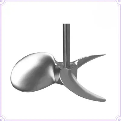
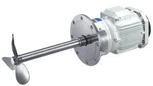
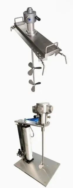
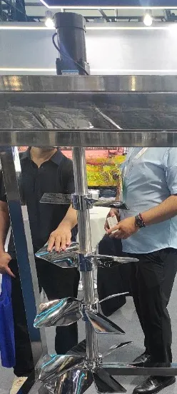
A marine propeller agitator is an axial-flow mixing device designed for low-viscosity fluids, generating strong bulk circulation through pitched propeller blades. Operating at low power consumption relative to the circulation volume achieved, it is the standard choice for large-volume homogeneous blending, liquid-liquid mixing, and heat transfer support in beverage, water treatment, pharmaceutical, and chemical processing vessels.
The propeller pushes liquid axially along the shaft direction, creating large-scale circulation loops from the impeller downward to the vessel base and back up the vessel walls. Baffles prevent solid body rotation and convert rotational momentum into productive axial flow. Correct impeller positioning at approximately one-third of the liquid height from the vessel base ensures bottom circulation and prevents dead zones.
Challenges
Viscosity Limitation
Axial circulation efficiency reduces significantly as fluid viscosity increases beyond approximately 2,000 cP, as the propeller can no longer generate sufficient bulk flow to maintain effective tank-wide circulation.
Vortex Formation Without Baffles
In unbaffled vessels, the rotating propeller induces solid body rotation and a surface vortex that draws air into the liquid, reducing mixing effectiveness and causing product aeration.
Insufficient Shear for Dispersion and Emulsification
The marine propeller generates bulk flow rather than localised high shear, making it unsuitable for emulsification, particle size reduction, or suspension of high concentrations of dense solids.
Stratification in Tall Vessels
In vessels with a high height-to-diameter ratio, a single propeller at the standard mounting position may not generate sufficient circulation to prevent density or temperature stratification in the upper liquid zones.
Dead Zones from Incorrect Impeller Positioning
Mounting the propeller too high or too low within the vessel reduces circulation coverage, leaving poorly mixed regions at the vessel base or upper liquid surface.
Solutions
- Four-Baffle Installation at 10% of Vessel Diameter: Installing four equally spaced baffles of width approximately 10% of vessel diameter suppresses vortex formation and converts rotational momentum into productive axial and radial bulk circulation throughout the vessel.
- Impeller Positioned at One-Third of Liquid Height from Base: Positioning the propeller at the standard one-third height from the vessel base maximises bottom circulation, prevents settled-solid accumulation, and ensures whole-vessel turnover efficiency.
- Second Propeller at Mid-Height for Tall Vessels: Installing a second propeller at mid-vessel height in vessels with height-to-diameter ratio above 1.5 eliminates stratification in the upper liquid zones and ensures uniform mixing across the full vessel height.
- Variable Frequency Drive with Soft-Start: Gradually ramping propeller speed at start-up prevents initial aeration and reduces mechanical shock to shaft and seals, while allowing speed adjustment to match mixing intensity to changing process conditions during the batch cycle.
- Side-Entry Mounting for Very Large Vessels: In large storage and process tanks where top-entry shaft length becomes impractical, a side-entry marine propeller with an angled shaft provides effective bulk circulation without requiring a long central shaft assembly.
Applications
- Water and Wastewater Treatment Chemical Dosing Mixing: Rapid homogenisation of coagulant, flocculant, and pH adjustment chemical doses into large water treatment tank volumes, ensuring uniform distribution of reagents throughout the bulk liquid at low power consumption.
- Beverage Blending and Flavour Integration: Uniform blending of juice concentrates, flavour additions, and sugar syrups into beverage bases in large-volume mixing tanks prior to filling, where gentle axial circulation achieves homogeneity without product aeration or foam generation.
- Pharmaceutical Aqueous Solution and Syrup Preparation: Mixing of aqueous pharmaceutical formulations, oral syrups, and liquid dosage form bases in GMP-rated vessels where low-shear axial circulation achieves uniform ingredient distribution without degrading dissolved active ingredients.
- Chemical Liquid-Liquid Blending and Dilution: Homogenisation of miscible liquid systems, solvent blending, and reagent dilution in chemical process vessels where efficient bulk turnover at low power input is the primary mixing requirement.
- Biotechnology Gentle Cell Culture Agitation: Low-shear bulk circulation in mammalian and insect cell culture vessels where adequate nutrient and oxygen distribution must be maintained without imposing mechanical shear levels that damage fragile cell membranes.
Models & Capacities
Model | Scale | Vessel Vol [L] | Propeller Ø DP [mm] | DP / DT Ratio | H / DT Range | Speed [RPM] | Tip Speed [m/s] | Motor Power [kW] | Power Density [kW/m³] | Pumping No. Nq | Circ. Flow [m³/h] | Blend Time T95 | Viscosity Max [cP] | Re (max) |
Lab Scale — 0.1 L to 10 L — Bench / Development | ||||||||||||||
JBM-MP-LAB-0.5 | Lab | 0.1 – 0.5 | 30 – 50 | 0.33 – 0.45 | 0.8 – 1.5 | 500 – 1,500 | 0.8 – 3.9 | 0.006 – 0.04 | 0.5 – 2.0 | 0.50 – 0.65 | 0.01 – 0.05 | < 2 min | 500 | > 10,000 |
JBM-MP-LAB-2 | Lab | 0.5 – 2 | 40 – 70 | 0.33 – 0.44 | 0.8 – 1.5 | 500 – 1,500 | 1.0 – 5.5 | 0.02 – 0.12 | 0.5 – 2.0 | 0.50 – 0.65 | 0.03 – 0.15 | < 2 min | 1,000 | > 15,000 |
JBM-MP-LAB-10 | Lab | 2 – 10 | 60 – 110 | 0.33 – 0.42 | 0.8 – 1.5 | 400 – 1,200 | 1.3 – 6.9 | 0.05 – 0.40 | 0.4 – 1.8 | 0.52 – 0.65 | 0.10 – 0.55 | < 3 min | 1,500 | > 20,000 |
Pilot Scale — 10 L to 1,000 L — Process Development & Scale-Up | ||||||||||||||
JBM-MP-PIL-50 | Pilot | 10 – 50 | 100 – 180 | 0.30 – 0.40 | 0.9 – 1.8 | 300 – 900 | 1.6 – 8.5 | 0.20 – 1.2 | 0.3 – 1.5 | 0.52 – 0.65 | 0.50 – 3.0 | < 3 min | 2,000 | > 30,000 |
JBM-MP-PIL-200 | Pilot | 50 – 200 | 160 – 280 | 0.30 – 0.38 | 1.0 – 2.0 | 200 – 700 | 1.7 – 10.3 | 0.60 – 4.0 | 0.3 – 1.2 | 0.53 – 0.66 | 2.0 – 10 | 1 – 5 min | 2,000 | > 40,000 |
JBM-MP-PIL-1000 | Pilot | 200 – 1,000 | 250 – 430 | 0.28 – 0.35 | 1.0 – 2.0 | 150 – 500 | 2.0 – 11.3 | 2.0 – 12 | 0.2 – 1.0 | 0.54 – 0.66 | 8 – 40 | 1 – 5 min | 2,000 | > 50,000 |
Production Scale — 1,000 L to 30,000 L — Industrial Manufacturing | ||||||||||||||
JBM-MP-P-3000 | Production | 1,000 – 3,000 | 380 – 600 | 0.27 – 0.33 | 1.0 – 2.0 | 120 – 400 | 2.4 – 12.6 | 7 – 35 | 0.2 – 0.9 | 0.55 – 0.67 | 25 – 130 | 2 – 8 min | 2,000 | > 60,000 |
JBM-MP-P-10000 | Production | 3,000 – 10,000 | 550 – 900 | 0.27 – 0.32 | 1.0 – 2.5 | 100 – 300 | 2.9 – 14.1 | 20 – 100 | 0.2 – 0.8 | 0.55 – 0.68 | 80 – 420 | 3 – 10 min | 2,000 | > 70,000 |
JBM-MP-P-30000 | Production | 10,000 – 30,000 | 800 – 1,300 | 0.26 – 0.33 | 1.0 – 2.5 | 80 – 250 | 3.4 – 17.0 | 55 – 280 | 0.2 – 0.7 | 0.56 – 0.68 | 250 – 1,300 | 4 – 12 min | 2,000 | > 80,000 |
Large Production — 30,000 L to 500,000 L — Bulk Storage & Processing | ||||||||||||||
JBM-MP-LP-100K | Large Prod | 30,000 – 100,000 | 1,200 – 1,900 | 0.25 – 0.32 | 1.0 – 2.5 | 60 – 180 | 3.8 – 17.9 | 150 – 750 | 0.2 – 0.6 | 0.56 – 0.69 | 800 – 4,000 | 5 – 15 min | 2,000 | > 90,000 |
JBM-MP-LP-500K | Large Prod | 100,000 – 500,000 | 1,800 – 3,000 | 0.22 – 0.30 | 1.0 – 3.0 | 40 – 120 | 3.8 – 18.8 | 400 – 2,000 | 0.2 – 0.5 | 0.57 – 0.70 | 3,000 – 16,000 | 6 – 20 min | 2,000 | > 100,000 |
Side-Entry Configuration — 50,000 L to 500,000 L — Large Tank Circulation (Horizontal Shaft, 7–15° Angle) | ||||||||||||||
JBM-MP-SE-50K | Side-Entry | 50,000 – 500,000 | 900 – 1,800 | 0.10 – 0.20 | 1.0 – 3.0 | 60 – 200 | 2.8 – 18.8 | 200 – 1,500 | 0.2 – 0.6 | 0.50 – 0.62 | 1,500 – 12,000 | 5 – 18 min | 2,000 | > 100,000 |