
Steam Manifold & Condensate Manifold
A distribution manifold is a fabricated SS 316L or carbon steel header pipe with multiple individually valved branch outlets — the steam manifold distributes supply steam from one main inlet to 2–24 process users at the correct pressure; the condensate manifold collects return condensate from 2–24 users and routes it to a single condensate return main. Both are available in DN 25–DN 300 header bore with branch outlets from DN 15 to DN 100, designed to ASME B31.1 / B31.3 or EN 13480 at pressures up to 32 bar(g) and temperatures up to 235°C.
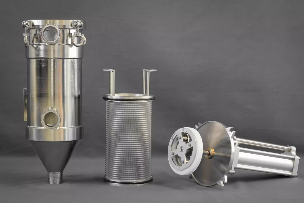
Steam enters the supply manifold header through the main inlet connection at full system pressure; individual branch ball or globe valves on each outlet allow operators to isolate or throttle supply to each user independently. Pressure gauges on each branch monitor user pressure. The condensate manifold receives condensate from individual trap outlets through check-valved branch inlets that prevent back-flow between branches — condensate combines in the header and flows to the return main. Both manifolds slope toward their respective drain/outlet points for self-draining between operating periods.
Challenges
Water Hammer from Condensate in Un-Drained Steam Manifold at Startup
Condensate accumulation in the steam manifold header during shutdown causes violent water hammer when steam flow is re-established.
Thermal Stress at Branch-to-Header Welds from Temperature Cycling
Daily heat-up and cool-down cycles impose cyclic thermal stress at branch weld toes — fatigue cracking over extended service.
Corrosion in Condensate Manifold from Dissolved Oxygen and CO₂
Dissolved oxygen and carbonic acid in condensate attack carbon steel condensate manifold internals — pitting corrosion and black iron contamination.
Pressure Equalisation Failure Across Long Manifold (Pressure Drop to Distant Branches)
Friction losses along the manifold header cause distant branch outlets to receive lower pressure than near branches.
Valve Passing (Seat Leakage) on Unused Branch Outlets Over Time
Branch isolating valves develop seat leakage over time — steam or condensate passes to an idle user line, wasting energy.
Solutions
- Automatic Drain Valve on Manifold Low Point (Opens on Shutdown Signal): PLC-controlled automatic drain valve opens on shutdown — removes all condensate before next startup; eliminates water hammer.
- Full-Penetration Butt Welds on All Branch-to-Header Connections (PWHT Where Required): Full-penetration welds with post-weld heat treatment eliminate stress concentrations — rated for 10,000 thermal cycles.
- SS 316L Condensate Manifold + Deaeration of Feedwater (Oxygen <10 ppb): Stainless manifold resists corrosion; upstream deaeration removes dissolved oxygen — eliminates corrosion source.
- Manifold Header Sized at 1.5× Maximum Branch Flow Velocity (<20 m/s Steam): Header sized for <20 m/s steam velocity — pressure drop across manifold length <0.05 bar at full load.
- Double-Block-and-Bleed (DBB) Valve on Each Unused Branch Outlet: DBB configuration provides two isolation points with bleed — confirmed zero leakage to idle lines.
Applications
- Pharmaceutical Manufacturing: Clean steam distribution to autoclaves, SIP stations, WFI stills, and CIP heat exchangers from one central header.
- Food & Beverage: Culinary steam supply to cooking vessels, pasteurisers, CIP heat exchangers, and process heat exchangers.
- Chemical Processing: Process steam supply to reactors, reboilers, heat exchangers, and distillation columns from header manifold.
- Power & Utilities: Low-pressure steam distribution manifold in auxiliary steam systems for heating and process services.
- Hospital & Sterile Services: Clean/pure steam distribution to sterilisers, instrument washers, and humidification units from central manifold.
Table A — Steam Supply Manifold: Models & Capacities
Steam Supply Manifold — Models & Capacities (DN 25 Header to DN 300 Header, 2–24 Outlets) | ||||||||||
Model | Header DN [mm] | Max Branch Outlets | Branch Outlet DN [mm] | Max Pressure [bar(g)] | Max Temp [°C] | Steam Flow (max) [kg/h] | Branch Valve Type | Drain Connection | Test Standard | Weight (bare) [kg] |
SM-025-02 | DN 25 | 2 | DN 15 | 32 | 235 | 60 | Ball valve BSP | DN 15 BSP | ASME B31.1 / EN 13480 | 8 |
SM-040-04 | DN 40 | 4 | DN 20 | 32 | 235 | 180 | Ball valve Tri-Clamp | DN 15 BW | ASME B31.1 / EN 13480 | 22 |
SM-050-06 | DN 50 | 6 | DN 25 | 32 | 235 | 400 | Ball valve Tri-Clamp | DN 20 BW | ASME B31.1 / EN 13480 | 38 |
SM-080-08 | DN 80 | 8 | DN 25–DN 40 | 25 | 220 | 900 | Globe valve flanged | DN 20 BW | ASME B31.1 / EN 13480 | 75 |
SM-100-12 | DN 100 | 12 | DN 25–DN 50 | 25 | 220 | 1,600 | Globe valve flanged | DN 25 BW | ASME B31.1 / EN 13480 | 130 |
SM-150-16 | DN 150 | 16 | DN 32–DN 65 | 16 | 200 | 3,500 | Globe valve flanged | DN 25 BW | ASME B31.1 / EN 13480 | 240 |
SM-200-20 | DN 200 | 20 | DN 40–DN 80 | 16 | 200 | 7,000 | Globe valve flanged | DN 32 BW | ASME B31.1 / EN 13480 | 420 |
SM-250-24 | DN 250 | 24 | DN 50–DN 100 | 10 | 185 | 12,000 | Gate valve flanged | DN 40 BW | ASME B31.1 / EN 13480 | 700 |
SM-300-24 | DN 300 | 24 | DN 65–DN 100 | 10 | 185 | 20,000 | Gate valve flanged | DN 50 BW | ASME B31.1 / EN 13480 | 1,100 |
Table B — Condensate Return Manifold: Models & Capacities
Condensate Return Manifold — Models & Capacities (DN 20 Header to DN 200 Header, 2–16 Inlets) | ||||||||||
Model | Header DN [mm] | Max Branch Inlets | Branch Inlet DN [mm] | Max Pressure [bar(g)] | Max Temp [°C] | Condensate Flow (max) [kg/h] | Check Valve per Inlet | Outlet Connection | Drain Connection | Weight (bare) [kg] |
CM-020-02 | DN 20 | 2 | DN 15 | 10 | 180 | 100 | Yes (SS check) | DN 20 BW/flanged | DN 15 BSP | 6 |
CM-032-04 | DN 32 | 4 | DN 15–DN 20 | 10 | 180 | 250 | Yes | DN 32 BW/flanged | DN 15 BSP | 14 |
CM-050-06 | DN 50 | 6 | DN 20–DN 25 | 10 | 180 | 600 | Yes | DN 50 BW/flanged | DN 20 BSP | 28 |
CM-080-08 | DN 80 | 8 | DN 25–DN 40 | 10 | 180 | 1,200 | Yes | DN 80 flanged | DN 20 BSP | 52 |
CM-100-10 | DN 100 | 10 | DN 25–DN 50 | 10 | 180 | 2,500 | Yes | DN 100 flanged | DN 25 BSP | 90 |
CM-150-12 | DN 150 | 12 | DN 40–DN 65 | 10 | 180 | 5,000 | Yes | DN 150 flanged | DN 25 BSP | 165 |
CM-200-16 | DN 200 | 16 | DN 50–DN 80 | 10 | 180 | 10,000 | Yes | DN 200 flanged | DN 32 BSP | 290 |