
Steam & Condensate Piping Network
The piping network conveys steam from the boiler or central header to process users and returns condensate to the boiler feedwater system — comprising steam mains (high-pressure distribution), steam sub-mains and branch lines (local distribution), condensate return mains (wet or dry return), drip legs (condensate collection pockets at low points and before equipment), and expansion loops or bellows (thermal growth accommodation). Designed to ASME B31.1 / B31.3 or EN 13480, the network operates at 1–32 bar(g) steam and 0.1–10 bar(g) condensate return pressure.
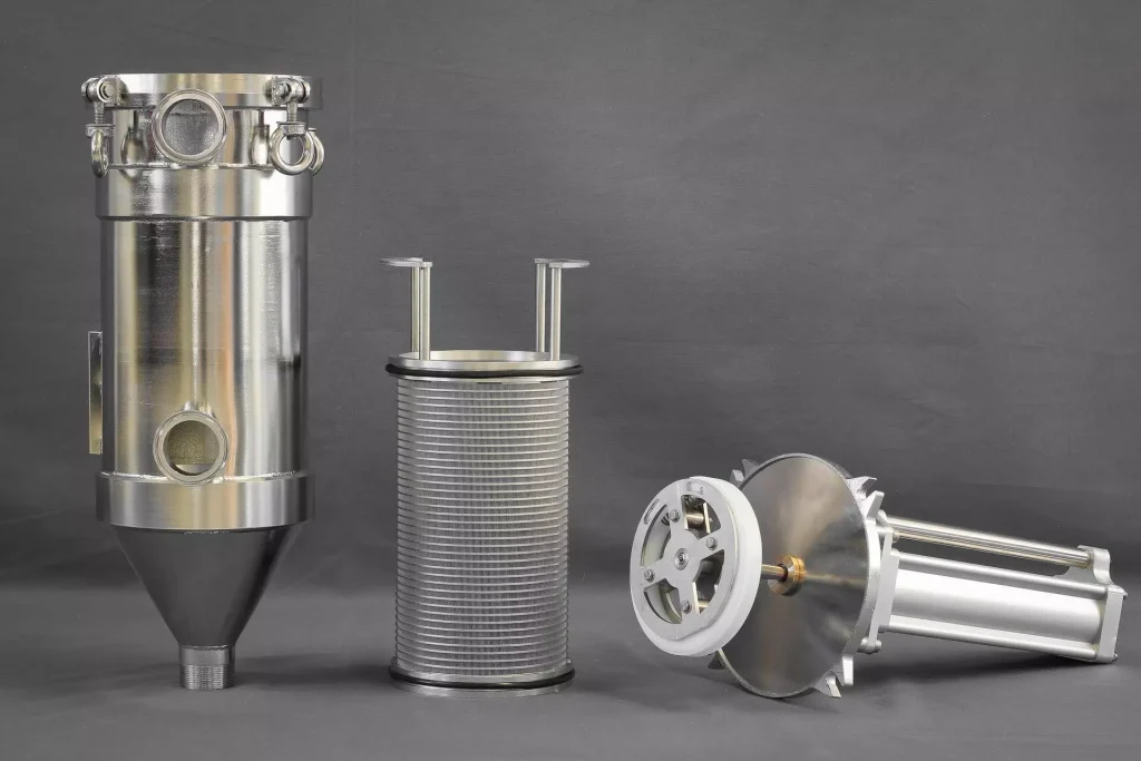
The piping network conveys steam from the boiler or central header to process users and returns condensate to the boiler feedwater system — comprising steam mains (high-pressure distribution), steam sub-mains and branch lines (local distribution), condensate return mains (wet or dry return), drip legs (condensate collection pockets at low points and before equipment), and expansion loops or bellows (thermal growth accommodation). Designed to ASME B31.1 / B31.3 or EN 13480, the network operates at 1–32 bar(g) steam and 0.1–10 bar(g) condensate return pressure.
Steam enters the main at boiler pressure and flows to sub-mains and branches; velocity is maintained at 20–35 m/s (saturated steam, DN 50–DN 600) to carry condensate droplets forward without pooling. Drip legs (typically 2–3× pipe diameter depth, 300–600 mm) collect condensate at low points and feed steam traps. The condensate return main uses gravity slope (minimum 1:240) or pumped return to convey condensate back. Expansion loops (U-loops, Z-loops, or bellows) accommodate thermal growth of 10–15 mm/m at 10 bar(g) — every straight run >15 m requires an expansion provision.
Challenges
Water Hammer from Condensate Accumulation in Steam Main at Startup or Low Load
Condensate pools in steam main horizontal runs at below-design steam velocity — slug flow causes severe water hammer.
Piping Sagging Between Supports Causing Low Points that Trap Condensate
Insufficient support spacing allows pipe creep between supports — creates unauthorised low points not drained by designed drip legs.
Thermal Expansion Stress Cracking at Fixed Anchor Points
Thermal growth restrained at fixed anchors generates compressive stress — pipe buckling or anchor point cracking over years.
Corrosion from Oxygen Ingress in Condensate Return Pipeline
Air ingress through steam trap vents, leaking pipe joints, or atmospheric flash vessels introduces oxygen — corrodes return mains.
Flash Steam Loss at Condensate Collection Points at High Back-Pressure
High condensate return line back-pressure prevents trap discharge — condensate backs up; steam space waterlogged.
Solutions
- Startup Drain Valves at All Low Points + Slow Warm-Up Protocol (ΔT <50°C/min): Open all drain points before steam admission; warm-up rate limited to 50°C/min — prevents thermal shock and water hammer.
- Maximum Support Spacing to Pipe Schedule (DN 25: max 2 m; DN 100: max 4 m; DN 200: max 5.5 m): Code-compliant support spacing prevents sag — eliminates unauthorised low points between designed drip legs.
- Loop Expansion Every 15 m Straight Run (U-Loop: minimum 3× pipe OD arm length): Pre-designed expansion loops accommodate full thermal growth — zero stress at anchor points.
- Closed Condensate Recovery System (Pressurised Return, Deaerator Head Tank): Fully closed system prevents air ingress — return maintained above atmospheric by back-pressure; oxygen ingress eliminated.
- Flash Steam Vessel + Flash Steam Recovery at Main Condensate Collection Points: Flash vessel at high-pressure condensate collection reduces back-pressure — traps discharge freely; flash steam used for low-pressure heating.
Applications
- Industrial Plants: Steam distribution networks for chemical, refinery, and power auxiliary systems — DN 50 to DN 600 at 1–32 bar(g).
- Pharmaceutical: GMP clean/pure steam distribution piping in SS 316L — orbital welded, Ra <0.8 µm, slope-to-drain.
- Food & Beverage: Culinary steam distribution in food-grade SS 316L — full-penetration welds, sloped to drain, GMP installation.
- Hospitals & Healthcare: Low-pressure steam distribution networks for sterilisers, CSSD, and space heating.
- District Heating: Pre-insulated steam and condensate return piping networks for campus or district energy systems.
Piping Sizing Reference
Steam Piping Network — Sizing & Capacity Reference (DN 15 to DN 600) | |||||||||
Schedule (SS 316L) | Max Steam Flow @ 25 m/s [kg/h] | Max Steam Flow @ 35 m/s [kg/h] | Design Pressure (ASME B31.1) [bar] | Max Temp [°C] | Max Support Spacing [mm] | Thermal Expansion (CS per 100°C) [mm/m] | Min Drip Leg Depth [mm] | Min Drip Leg DN [mm] |
|
Sch 10S | 30 | 42 | 32 | 400 | 1,800 | 1.2 | 150 | DN 15 |
|
Sch 10S | 55 | 77 | 32 | 400 | 2,000 | 1.2 | 200 | DN 15 |
|
Sch 10S | 110 | 150 | 32 | 400 | 2,000 | 1.2 | 300 | DN 20 |
|
Sch 10S | 175 | 245 | 32 | 400 | 2,500 | 1.2 | 400 | DN 20 |
|
Sch 10S | 280 | 395 | 25 | 400 | 2,500 | 1.2 | 400 | DN 20 |
|
Sch 10S | 500 | 700 | 25 | 400 | 3,000 | 1.2 | 500 | DN 25 |
|
Sch 10S | 850 | 1,190 | 25 | 400 | 3,000 | 1.2 | 500 | DN 25 |
|
Sch 10S | 1,200 | 1,700 | 25 | 400 | 3,500 | 1.2 | 600 | DN 25 |
|
Sch 10S | 2,000 | 2,800 | 25 | 400 | 4,000 | 1.2 | 600 | DN 32 |
|
Sch 10S | 3,000 | 4,200 | 16 | 400 | 4,500 | 1.2 | 700 | DN 32 |
|
Sch 10S | 4,500 | 6,300 | 16 | 400 | 5,000 | 1.2 | 700 | DN 40 |
|
Sch 10S | 8,000 | 11,200 | 16 | 400 | 5,500 | 1.2 | 800 | DN 40 |
|
Sch 10S | 14,000 | 19,500 | 10 | 350 | 6,000 | 1.2 | 900 | DN 50 |
|
Sch 10S | 20,000 | 28,000 | 10 | 350 | 6,000 | 1.2 | 1,000 | DN 50 |
|
— | 40,000 | 56,000 | 10 | 350 | 6,500 | 1.2 | 1,200 | DN 65 |
|
— | 65,000 | 90,000 | 10 | 350 | 7,000 | 1.2 | 1,500 | DN 80 |
|
— | 100,000 | 140,000 | 6 | 300 | 7,500 | 1.2 | 1,800 | DN 80 |
|