
Overhead Mechanical Stirrer
Category Overview
Multi-impeller overhead mechanical stirrers extend single-impeller designs with two or more staged impeller assemblies on a common shaft, delivering more uniform mixing across tall vessels where a single impeller would leave poorly mixed regions. Used across laboratory and production scales, they are suited to applications involving tall vessel geometries, stratified fluids, and processes requiring consistent shear and flow distribution across the full vessel height.
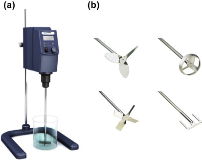
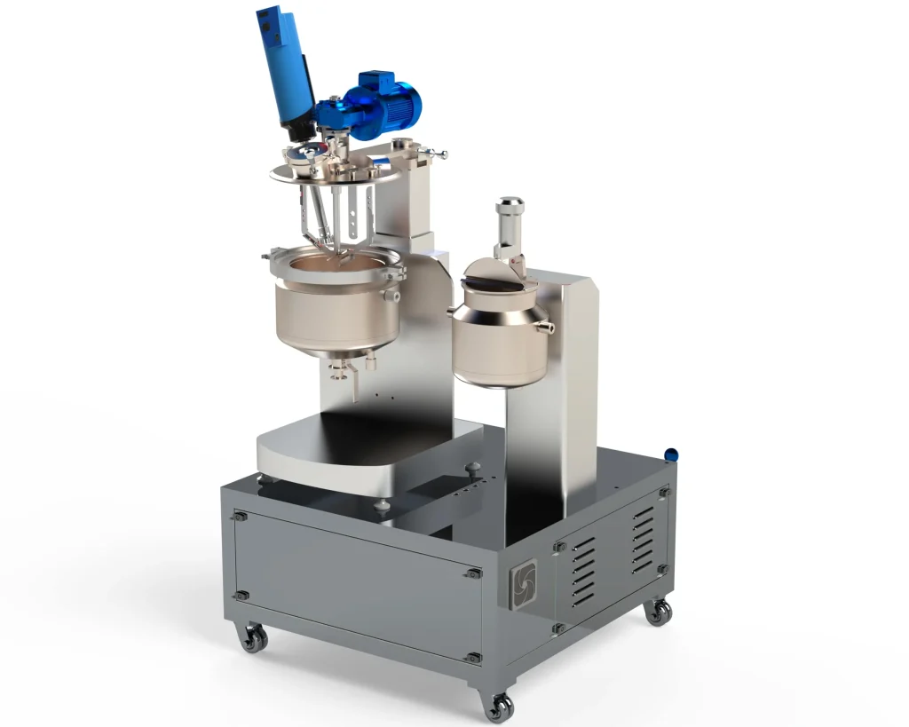
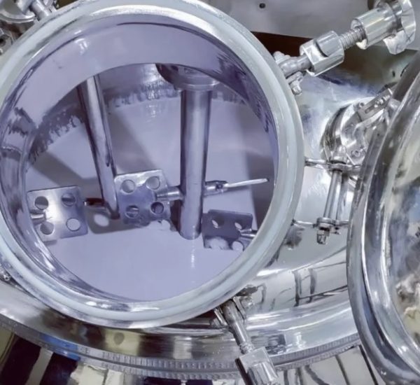
A multi-impeller overhead mechanical stirrer features two or more impellers mounted at defined vertical intervals on a single rotating shaft driven by a variable-speed motor. Impeller types are selected based on the application, with common choices including pitched-blade turbines, hydrofoil impellers, and anchor types. The configuration is used in tall vessels where a single impeller cannot provide adequate circulation across the full liquid height, and is applied in reaction, crystallisation, suspension, and blending duties.
The motor drives the central shaft through a bearing assembly, with all impellers rotating at the same shaft speed. Each impeller generates a flow pattern suited to its geometry: hydrofoil and pitched-blade impellers promote axial bulk circulation, while radial turbines deliver higher local power input. The vertical spacing between impellers is selected to avoid flow interference between adjacent impellers while ensuring overlapping circulation zones cover the full vessel height. Vessel baffles suppress solid body rotation and convert rotational momentum into three-dimensional bulk flow. The combination of impeller type, spacing, and baffle geometry determines the overall mixing performance across the vessel.
Challenges
Dead Zones Between Impellers
In tall vessels, insufficient overlap between adjacent impeller circulation zones can leave poorly mixed regions between impellers, particularly at low flow rates or high viscosity.
Uneven Power Distribution Across Impellers
In fluids with density gradients or during processes where local viscosity varies with height, different impellers on the same shaft experience different resistance, making uniform power distribution difficult to achieve.
Shaft Vibration at Certain Operating Speeds
Long shafts operating at speeds that approach the shaft natural frequency can develop vibration, causing mechanical stress and accelerated bearing wear.
Scale-Up Uncertainty
Mixing behaviour observed at laboratory scale in multi-impeller configurations does not always translate directly to larger vessels due to changes in fluid dynamics with vessel geometry.
High Torque Demand at Elevated Viscosity
At high viscosities, the torque required to maintain adequate impeller speed can exceed the motor and gearbox capacity, limiting operating range.
Solutions
- Optimised Impeller Spacing and Selection: Impeller type and vertical spacing are selected based on vessel geometry and fluid properties to ensure overlapping circulation zones and minimise poorly mixed regions.
- Variable Frequency Drive: Allows operating speed to be adjusted in response to changing fluid properties during the process, keeping torque demand within motor capacity while maintaining adequate mixing.
- Critical Speed Identification and Avoidance: The shaft critical speed is calculated during design and the operating speed range is set to avoid sustained operation near resonance, reducing vibration risk.
- Geometrically Consistent Scale-Up Approach: Maintaining consistent ratios of impeller diameter to tank diameter and impeller spacing to impeller diameter between scales improves the reliability of scale-up predictions.
- High-Torque Gearmotor Selection: Specifying the drive system based on the maximum expected torque demand at the highest process viscosity ensures the motor and gearbox can sustain operation throughout the full batch cycle.
Applications
- Antibiotic Crystallisation (e.g., Amoxicillin, Cephalexin): Controlled anti-solvent addition and crystal suspension in tall crystalliser vessels where uniform shear prevents crystal breakage and controls polymorphic form.
- Vaccine Adjuvant Suspension (e.g., Aluminium Hydroxide Suspensions): Uniform particle suspension and gentle bulk circulation maintaining consistent particle distribution without settling or agglomeration.
- Fermentation Broths (e.g., Penicillin, Citric Acid, Ethanol): Oxygen distribution and bulk circulation across tall bioreactor vessels during aerobic fermentation.
- Polymer Solution Blending (e.g., Polyvinylpyrrolidone, Hydroxypropyl Methylcellulose Solutions): Homogenisation of high-viscosity polymer solutions used as binders and film-coating bases in tablet manufacturing.
- Resin Pre-Polymerisation (e.g., Epoxy Resin, Polyester Resin): Bulk circulation and temperature management during exothermic pre-polymerisation stages before viscosity becomes too high for overhead stirring.
- Pesticide Suspension Concentrates (e.g., Herbicide and Fungicide Suspensions): Uniform active ingredient suspension in tall mixing vessels prior to filling.
- Lithium-Ion Battery Electrolyte Blending: Homogeneous mixing of electrolyte salts into solvent systems in tall vessels under controlled atmosphere.
- Fruit Juice Concentrate Blending: Uniform incorporation of flavour concentrates, preservatives, and sugar syrups in tall food-grade vessels prior to filling operations.
Models & Capacities
| Model | Scale | Vessel Vol [L] | Max Viscosity [cP] | Impellers [#/Type] | Max RPM | Max Torque [Nm] | Shaft Length [mm] | Motor [kW] | Motor Type | Overall H [mm] | Weight [kg] |
|---|---|---|---|---|---|---|---|---|---|---|---|
| MIS-LAB-3 | Lab | 1-10 | 50,000 | 2/Pitched-Hydrofoil | 3,000 | 5 | 400 | 0.37 | AC VFD | 800 | 25 |
| MIS-LAB-5 | Lab | 5-25 | 75,000 | 3/Turbine-Hydrofoil | 2,500 | 10 | 600 | 0.75 | AC VFD | 1,000 | 38 |
| MIS-PIL-10 | Pilot | 20-100 | 100,000 | 3/Anchor-Pitched | 2,000 | 25 | 900 | 1.5 | Gearmotor | 1,400 | 85 |
| MIS-PIL-25 | Pilot | 50-250 | 100,000 | 4/Hydrofoil-Turbine | 1,800 | 50 | 1,200 | 3.0 | Gearmotor | 1,800 | 150 |
| MIS-P-50 | Production | 100-500 | 100,000 | 4/Pitched-Turbine-Anchor | 1,500 | 100 | 1,600 | 5.5 | Gearmotor | 2,300 | 320 |
| MIS-P-150 | Production | 300-1,500 | 100,000 | 5/Multi-stage | 1,200 | 200 | 2,200 | 11 | Gearmotor | 3,000 | 650 |
| MIS-P-500 | Production | 1,000-5,000 | 100,000 | 6/Full Coverage | 1,000 | 500 | 3,000 | 22 | Gearmotor | 4,000 | 1,800 |