
Single-Stage Centrifugal Pump
A single-stage centrifugal pump uses one radial or mixed-flow impeller rotating at 1,450–3,000 RPM to generate centrifugal force that accelerates fluid from the eye to the volute casing, converting velocity to pressure. Delivering 0.5–2,000 m³/h at heads to 150 m and 1–500 cP, it is the most widely used pump type in chemical, food, pharmaceutical, and water service optimised for continuous high-volume low-viscosity transfer.
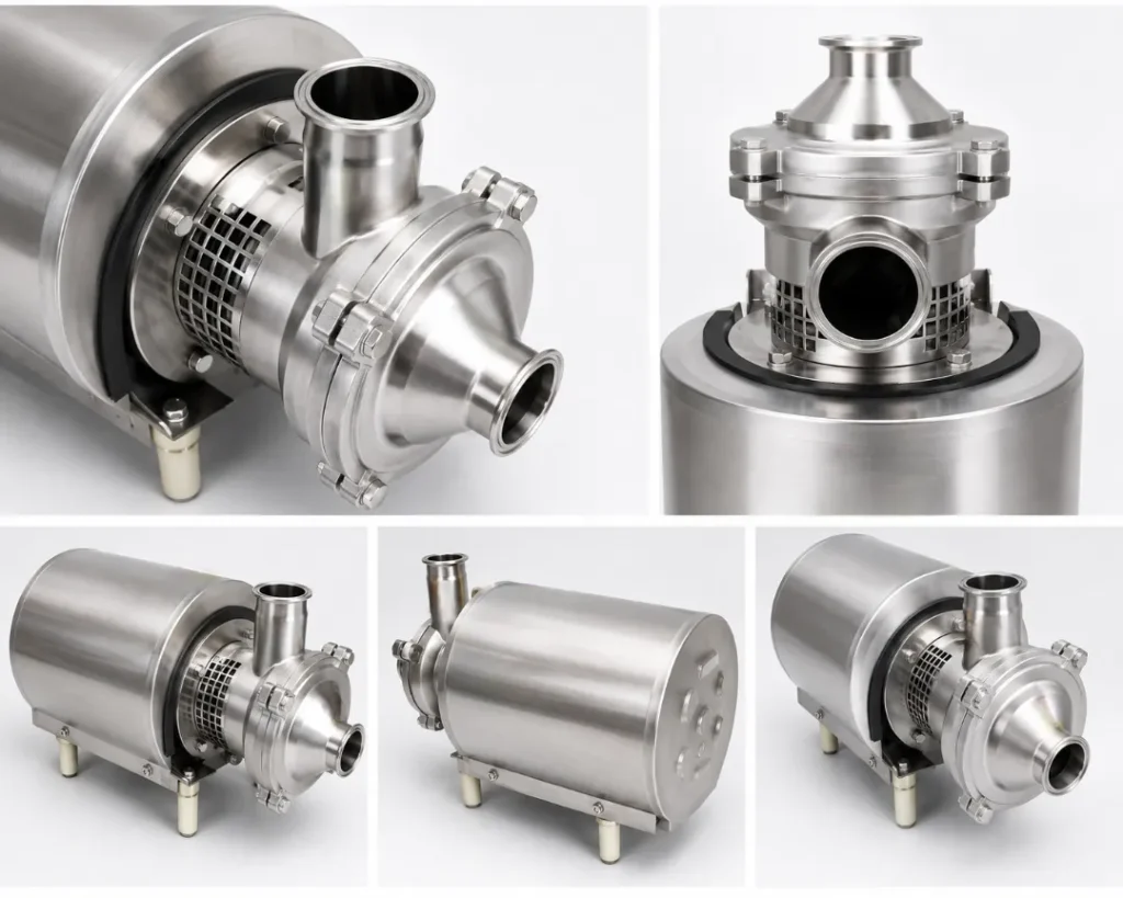
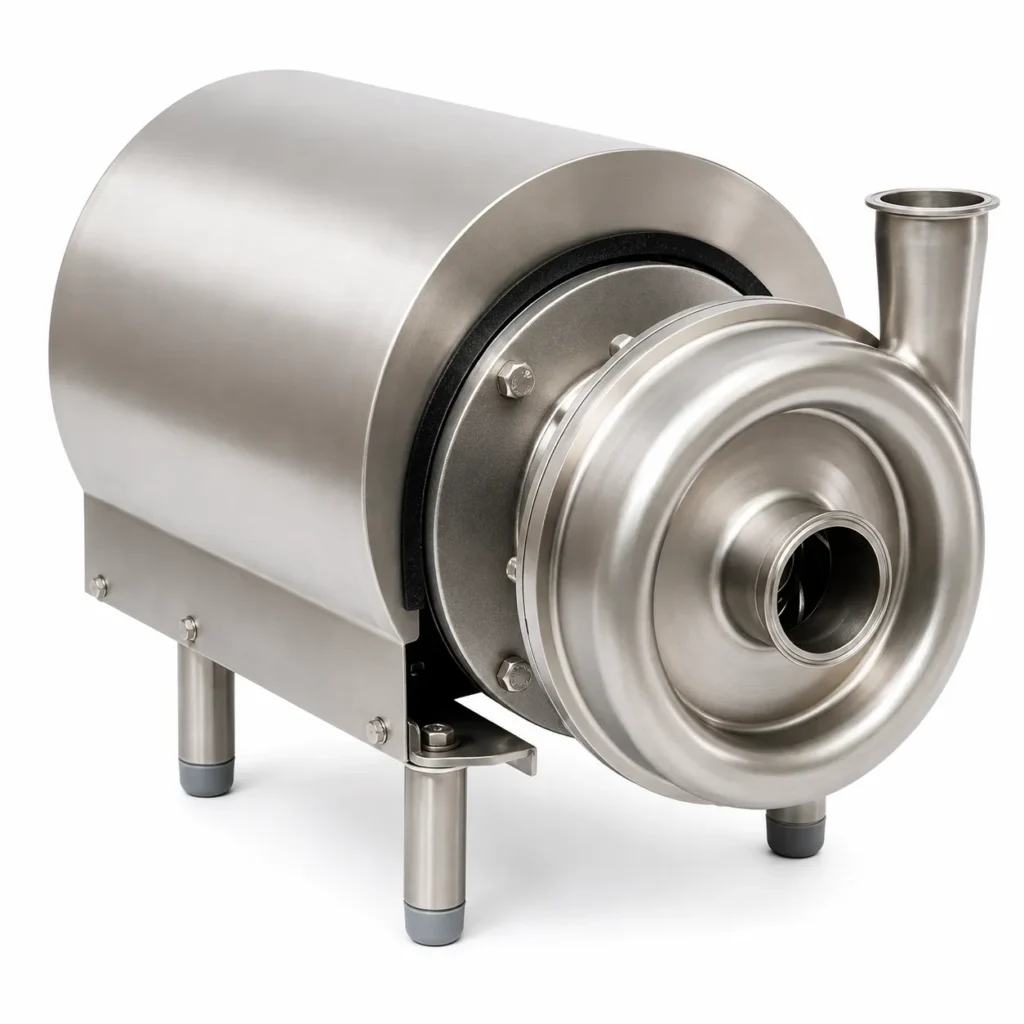
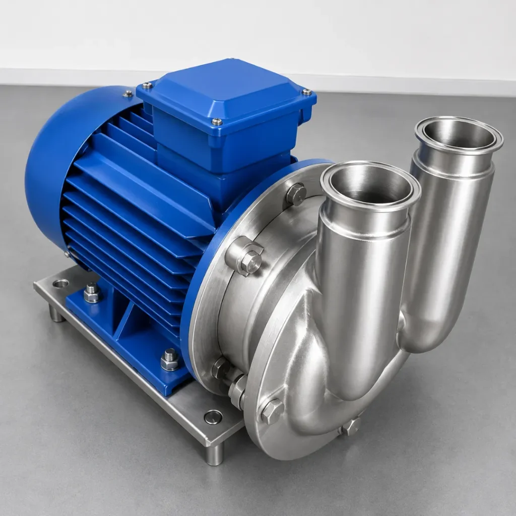
A single-stage centrifugal pump uses one radial or mixed-flow impeller rotating at 1,450–3,000 RPM to generate centrifugal force that accelerates fluid from the eye to the volute casing, converting velocity to pressure. Delivering 0.5–2,000 m³/h at heads to 150 m and 1–500 cP, it is the most widely used pump type in chemical, food, pharmaceutical, and water service optimised for continuous high-volume low-viscosity transfer.
Fluid enters axially at the impeller eye; rotating impeller blades (1,450–3,000 RPM) accelerate fluid radially outward by centrifugal force. The expanding volute casing converts kinetic energy to pressure (static head) as fluid decelerates. Performance is described by the pump curve intersection with the system curve defines operating duty point. Single-stage achieves up to 150 m head; impeller diameter and speed adjustment shift the curve to meet varying duty requirements.
Challenges
Low Efficiency at Partial Flow Rate
Operating far from best-efficiency point (BEP) reduces efficiency by 15–30%.
Cavitation at Low NPSH Available
Inlet pressure below vapour pressure causes bubble collapse, eroding impeller and volute.
Not Self-Priming (Standard Design)
Standard centrifugal cannot pump gas; requires flooded suction or priming arrangement.
Rapid Efficiency Loss Above 500 cP
Viscous drag on impeller sharply reduces head, flow, and efficiency above medium viscosity.
Seal Leakage in Aggressive Services
Single mechanical seal requires frequent replacement in corrosive or abrasive fluids.
Solutions
- VFD Speed Control (50–100% Speed): Operating at reduced speed maintains BEP efficiency at varying flow rates.
- NPSH Analysis and Suction Pipe Optimisation: Reducing suction velocity and eliminating elbows near pump prevents cavitation onset.
- Self-Priming Variant (Side-Channel or Recirculation Priming): Self-primes from up to 6 m suction lift eliminates foot valve and priming labour.
- Viscosity-Corrected Pump Selection (Hydraulic Institute Method): De-rating factor applied to BEP flow/head/efficiency curves for viscous service.
- Double Mechanical Seal with API-682 Plan 53B Barrier: Pressurised barrier fluid maintains seal face lubrication in aggressive/abrasive service.
Applications
- Water & Wastewater: Water supply, irrigation, cooling water, HVAC, effluent transfer, and dosing systems.
- Food & Beverage: Water-thin liquid transfer, CIP return, beverage processing, and ingredient blending.
- Chemical: Solvent, acid, alkali, and low-viscosity chemical transfer in continuous process service.
- Pharmaceutical: WFI and purified water distribution, CIP supply, low-viscosity liquid formulation transfer.
- Dairy: Milk, whey, and low-viscosity dairy liquid transfer and CIP circuit supply.
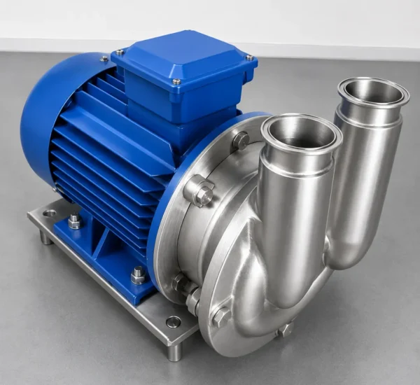
Product Catalogue & Technical Datasheet
Model | Flow Rate (m³/h) | Head (m) | Speed (RPM) | Motor (kW) | Viscosity Max (cP) | Inlet/Outlet Ø (DN) | NPSH Required (m) | L × W × H (mm) | Weight (kg) |
CP-S-003 | 0.5–3 | 5–30 | 2,900 | 0.18–0.37 | 500 | DN 25 / DN 20 | 1.5–3 | 280×150×220 | 8 |
CP-S-020 | 3–20 | 10–60 | 2,900 | 0.55–3.0 | 500 | DN 50 / DN 40 | 2–4 | 380×200×290 | 18 |
CP-S-100 | 20–100 | 15–80 | 2,900 | 3.0–11 | 500 | DN 80 / DN 65 | 2–4 | 540×280×380 | 42 |
CP-S-300 | 80–300 | 20–100 | 2,900 | 11–37 | 500 | DN 100 / DN 80 | 2–5 | 720×380×500 | 95 |
CP-S-800 | 200–800 | 25–120 | 1,450 | 37–90 | 500 | DN 150 / DN 125 | 2–5 | 1,050×520×680 | 220 |
CP-S-2000 | 600–2,000 | 30–150 | 1,450 | 90–220 | 500 | DN 200 / DN 200 | 2–6 | 1,500×700×900 | 520 |