
Ruvastar Cyclo Agitator
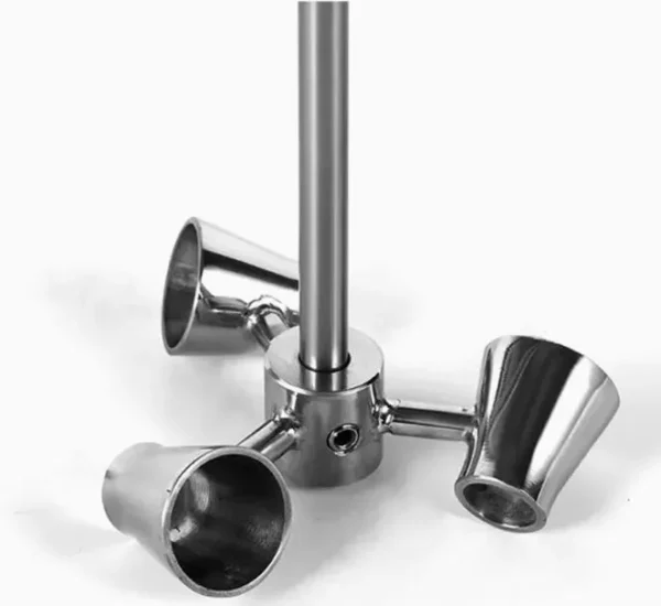
A Ruvastar Cyclo agitator is an advanced high-efficiency mixing system combining axial, radial, and tangential cyclonic flow for superior mixing and dispersion across 1-50,000 cP (Re 1,000 to >10,000). Operating at 50-500 RPM with power consumption of 0.5-6 kW/m3, it delivers up to 50% energy savings versus conventional impellers while achieving mass transfer coefficients of 10^-4 to 10^-3 m/s and U values of 300-1,200 W/m2K -- ideal for large-scale fermentation and complex multiphase systems.
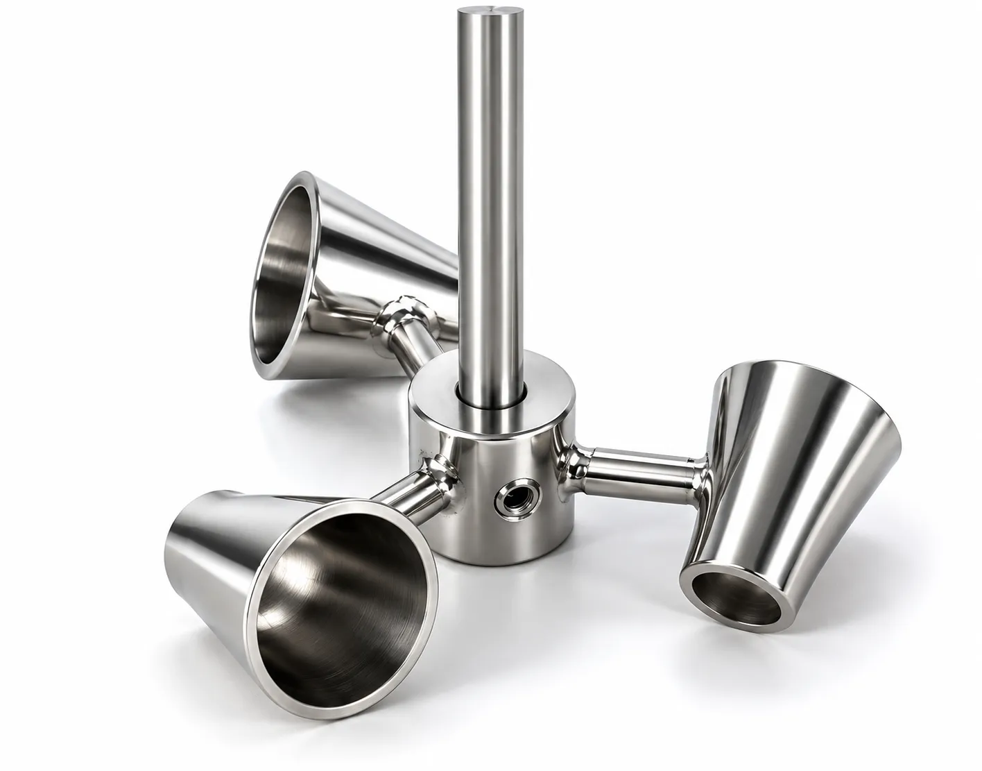
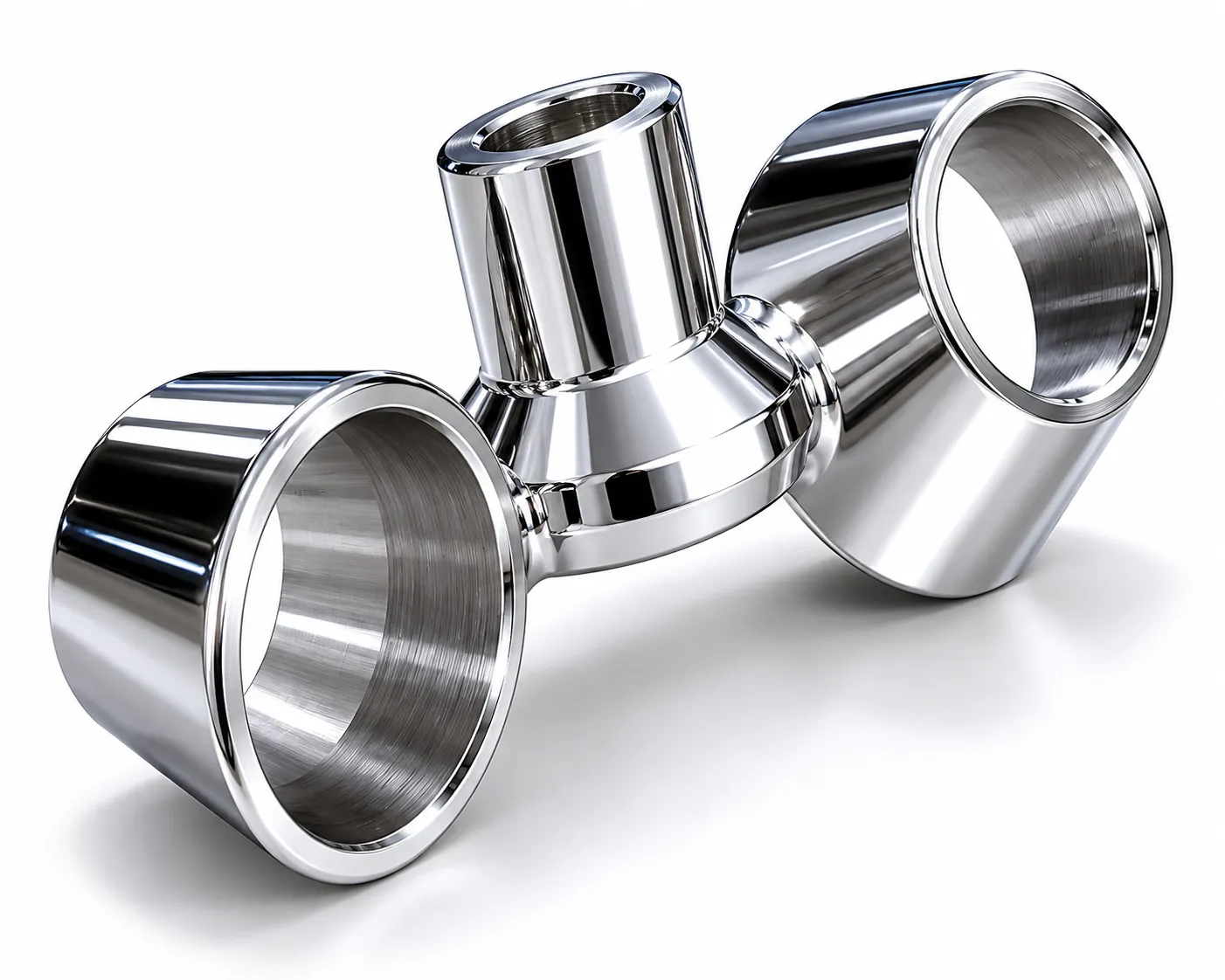
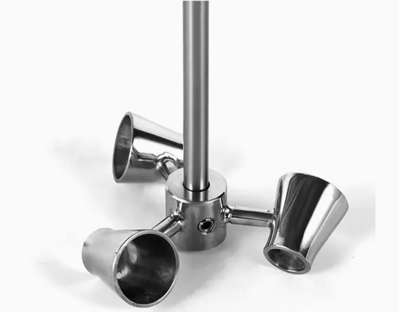
A Ruvastar Cyclo agitator is an advanced high-efficiency mixing system combining axial, radial, and tangential cyclonic flow for superior mixing and dispersion across 1-50,000 cP (Re 1,000 to >10,000). Operating at 50-500 RPM with power consumption of 0.5-6 kW/m3, it delivers up to 50% energy savings versus conventional impellers while achieving mass transfer coefficients of 10^-4 to 10^-3 m/s and U values of 300-1,200 W/m2K — ideal for large-scale fermentation and complex multiphase systems.
The cyclonic impeller generates simultaneous axial, radial, and tangential velocity components, establishing a three-dimensional rotating flow field that eliminates dead zones throughout the vessel volume. High internal circulation rates ensure rapid temperature and concentration equalisation. The multi-directional flow pattern is particularly effective in minimising shear damage to sensitive biological cultures while maintaining mass transfer performance equivalent to conventional high-speed Rushton turbines at significantly lower power input.
Challenges
Complex Impeller Fabrication
Multi-directional blade geometry increases casting and machining complexity and cost.
Higher Capital Cost
Advanced cyclonic geometry commands a premium over standard axial or radial impellers.
Application-Specific Selection
Cyclonic performance requires careful CFD validation for each specific vessel and process.
Maintenance of Cyclonic Geometry
Blade profile damage disrupts flow pattern symmetry more severely than for simple impellers.
Power Optimisation Required
Energy savings realised only when impeller-to-tank ratio and speed are properly matched.
Solutions
- CFD-Validated Impeller-Tank Matching: D/T ratio and blade angle optimised per vessel geometry; ensures target cyclonic pattern.
- VFD Speed Control: Continuously adjusts cyclonic intensity to match process conditions; achieves target km at minimum kW/m3.
- Robust Impeller Construction: Investment-cast SS 316L blades with electropolished finish withstand continuous operation.
- Energy Benchmarking vs. Rushton: Demonstrated 30-50% power reduction at equivalent k_La for fermentation applications.
- Modular Blade Replacement: Individual blades replaceable without full impeller removal to minimise maintenance downtime.
- Improved RTD Uniformity: Cyclonic pattern narrows residence time distribution; reduces concentration variance vs. axial-only flow.
Applications
- Chemical: Complex reactions, blending, emulsification, and multi-phase mixing requiring high circulation.
- Pharmaceutical: Suspensions, liquid formulations, API mixing, and large-scale sterile manufacturing.
- Biotechnology: Large-scale aerobic fermentation, bioreactor agitation, and shear-sensitive cell culture.
- Food & Beverage: Syrups, beverages, sauces, and emulsion stabilisation at large production volumes.
- Cosmetics: Creams, lotions, gels, and emulsified product manufacture at commercial scale.
- Water Treatment: Chemical mixing, dosing, coagulation, and flocculation in large municipal tanks.
- Paints & Coatings: Pigment dispersion, blending, and viscosity control in coating production vessels.
Models & Capacities
Model | Scale | Vessel Vol [L] | Impeller Ø D [mm] | D / T Ratio | No. Impellers | Speed [RPM] | Tip Speed [m/s] | Motor Power [kW] | Power Density [kW/m³] | Power No. Np | Pumping No. Nq | kLa [s⁻¹] | Viscosity Max [cP] | Re (max) | |
Single Ruvastar Cyclo (RVC-1) — 0.5 L Lab to 500,000 L Large Production — Cyclonic Axial-Radial-Tangential Flow; 30–50% Power Saving vs. Rushton at Equal kLa | |||||||||||||||
RVC-1-LAB-1 | Lab | 0.5 – 1 | 50 – 80 | 0.30 – 0.45 | 1 | 200 – 500 | 0.5 – 2.1 | 0.005 – 0.05 | 0.5 – 3.0 | 1.8 – 3.0 | 0.65 – 0.80 | 0.01 – 0.15 | 5,000 | > 5,000 | |
RVC-1-LAB-5 | Lab | 1 – 5 | 70 – 130 | 0.30 – 0.45 | 1 | 150 – 500 | 0.5 – 3.4 | 0.01 – 0.12 | 0.5 – 3.0 | 1.8 – 3.0 | 0.65 – 0.82 | 0.01 – 0.18 | 10,000 | > 8,000 | |
RVC-1-LAB-20 | Lab | 5 – 20 | 110 – 200 | 0.30 – 0.45 | 1 | 100 – 400 | 0.6 – 4.2 | 0.03 – 0.40 | 0.5 – 3.0 | 1.8 – 3.0 | 0.66 – 0.82 | 0.01 – 0.18 | 15,000 | > 10,000 | |
RVC-1-PIL-100 | Pilot | 20 – 100 | 175 – 320 | 0.30 – 0.45 | 1 | 80 – 300 | 0.7 – 5.0 | 0.10 – 1.5 | 0.4 – 2.5 | 1.8 – 3.0 | 0.66 – 0.82 | 0.008 – 0.15 | 20,000 | > 12,000 | |
RVC-1-PIL-500 | Pilot | 100 – 500 | 280 – 500 | 0.30 – 0.45 | 1 | 60 – 200 | 0.9 – 5.2 | 0.40 – 5.0 | 0.4 – 2.2 | 1.9 – 3.0 | 0.67 – 0.83 | 0.006 – 0.12 | 30,000 | > 15,000 | |
RVC-1-P-2000 | Production | 500 – 2,000 | 450 – 800 | 0.30 – 0.45 | 1 | 50 – 150 | 1.2 – 6.3 | 1.5 – 18 | 0.4 – 2.0 | 2.0 – 3.0 | 0.68 – 0.83 | 0.005 – 0.10 | 40,000 | > 20,000 | |
RVC-1-P-10000 | Production | 2,000 – 10,000 | 750 – 1,350 | 0.30 – 0.45 | 1 | 40 – 120 | 1.6 – 8.5 | 6 – 70 | 0.3 – 1.8 | 2.0 – 3.0 | 0.68 – 0.84 | 0.004 – 0.08 | 50,000 | > 30,000 | |
RVC-1-LP-50K | Large Prod | 10,000 – 50,000 | 1,200 – 2,200 | 0.28 – 0.40 | 1 | 25 – 80 | 1.6 – 9.2 | 25 – 200 | 0.3 – 1.5 | 2.0 – 3.0 | 0.68 – 0.84 | 0.003 – 0.06 | 50,000 | > 50,000 | |
RVC-1-LP-500K | Large Prod | 50,000 – 500,000 | 2,000 – 3,800 | 0.25 – 0.38 | 1 | 15 – 50 | 1.6 – 9.9 | 80 – 800 | 0.2 – 1.0 | 2.0 – 3.0 | 0.68 – 0.84 | 0.002 – 0.04 | 50,000 | > 80,000 | |
Multi-Stage Cyclo: Dual & Triple (RVC-D / RVC-T) — 50 L Pilot to 10,000 L Production — H/DT > 1.2; Impeller Spacing 1×D; Eliminates Stratification in Tall Vessels | |||||||||||||||
RVC-D-PIL-200 | Pilot / Dual | 50 – 200 | 175 – 320 | 0.30 – 0.45 | 2 | 80 – 300 | 0.7 – 5.0 | 0.20 – 3.0 | 0.4 – 2.5 | 1.9 – 3.0 | 0.67 – 0.83 | 0.010 – 0.22 | 30,000 | > 15,000 | |
RVC-D-P-2000 | Prod / Dual | 500 – 2,000 | 450 – 800 | 0.30 – 0.45 | 2 | 50 – 150 | 1.2 – 6.3 | 3.0 – 35 | 0.4 – 2.2 | 2.0 – 3.0 | 0.68 – 0.83 | 0.008 – 0.18 | 40,000 | > 25,000 | |
RVC-D-P-10000 | Prod / Dual | 2,000 – 10,000 | 750 – 1,350 | 0.30 – 0.45 | 2 | 40 – 120 | 1.6 – 8.5 | 12 – 130 | 0.4 – 2.0 | 2.0 – 3.0 | 0.68 – 0.84 | 0.006 – 0.15 | 50,000 | > 35,000 | |
RVC-T-P-5000 | Prod / Triple | 1,000 – 5,000 | 550 – 950 | 0.30 – 0.45 | 3 | 50 – 150 | 1.4 – 7.5 | 8 – 55 | 0.5 – 2.5 | 2.0 – 3.0 | 0.68 – 0.84 | 0.008 – 0.18 | 50,000 | > 25,000 | |
Ruvastar Cyclo + Rushton Combination (RVC-CR) — 50 L Pilot to 10,000 L Production — Lower Rushton for Gas Dispersion; Upper Cyclo for Bulk Circulation; Maximum kLa at Minimum kW/m³ | |||||||||||||||
RVC-CR-PIL-200 | Pilot / G-L | 50 – 200 | 175 – 320 | 0.30 – 0.45 | 2 | 80 – 300 | 0.7 – 5.0 | 0.30 – 3.5 | 0.5 – 3.0 | 2.5 – 4.5 | 0.60 – 0.78 | 0.015 – 0.30 | 20,000 | > 15,000 | |
RVC-CR-P-2000 | Prod / G-L | 500 – 2,000 | 450 – 800 | 0.30 – 0.45 | 2 | 50 – 150 | 1.2 – 6.3 | 2.5 – 25 | 0.5 – 3.0 | 2.5 – 4.5 | 0.62 – 0.78 | 0.012 – 0.25 | 30,000 | > 25,000 | |
RVC-CR-P-10000 | Prod / G-L | 2,000 – 10,000 | 750 – 1,350 | 0.30 – 0.45 | 2 | 40 – 120 | 1.6 – 8.5 | 10 – 100 | 0.5 – 2.5 | 2.5 – 4.5 | 0.62 – 0.78 | 0.010 – 0.22 | 40,000 | > 35,000 | |