
Redler (En-Masse) Chain Conveyor -- Multi-Directional
A Redler-type multi-directional en-masse chain conveyor uses T- or U-shaped paddle elements attached to a central roller chain -- moving bulk solid simultaneously in both the upper (loaded) and lower (return) runs of the casing with a single chain drive. Processing 0.2-50 t/h horizontally, on inclines, vertically, and around multiple direction changes in a single continuous casing path, it enables complex routing of powder and granules between production floors and areas inaccessible to belt or screw conveyors -- all within a single dust-tight enclosed circuit.
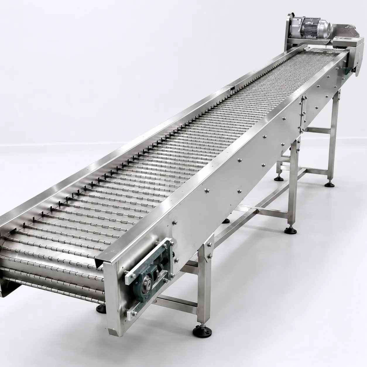
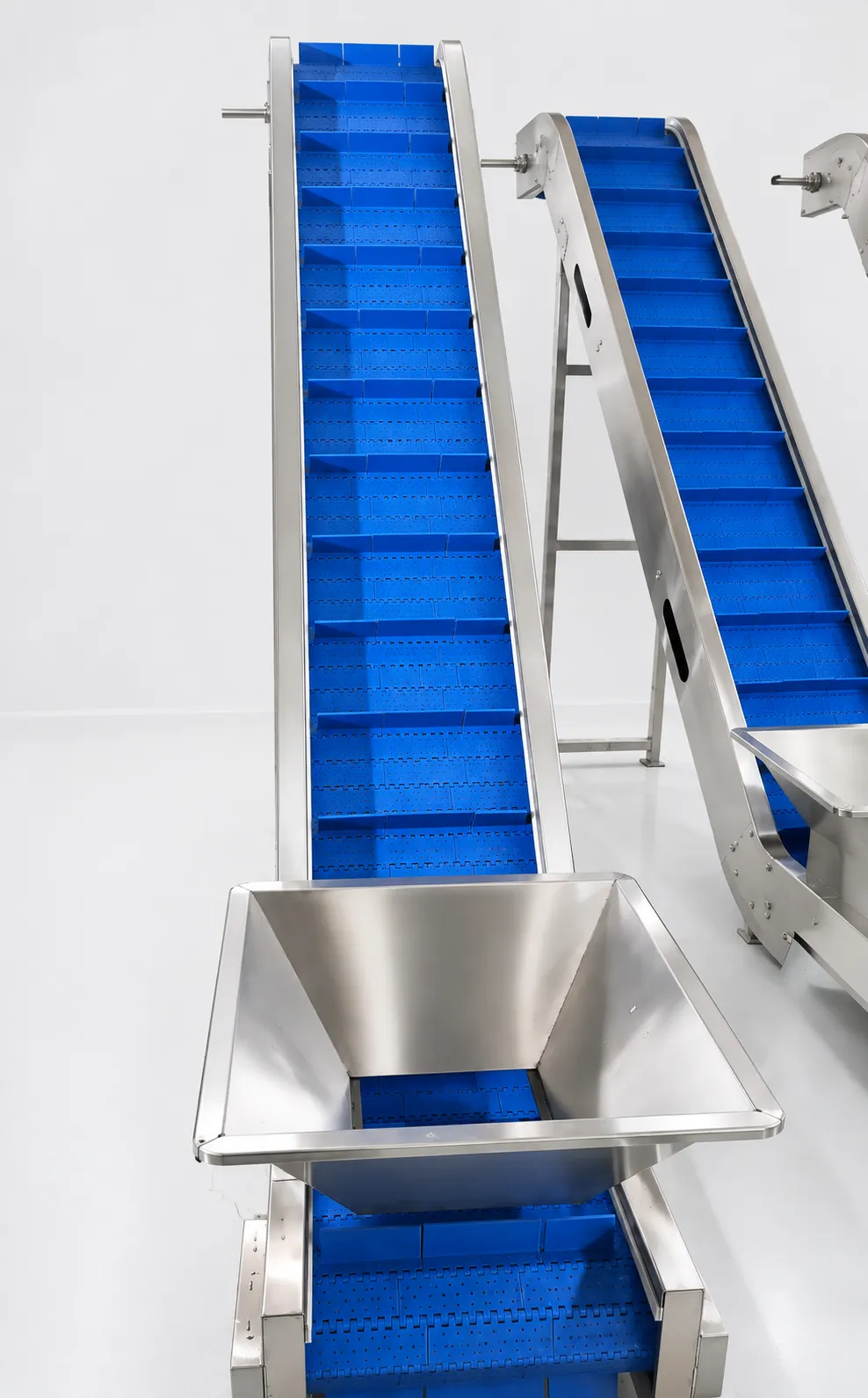
A Redler-type multi-directional en-masse chain conveyor uses T- or U-shaped paddle elements attached to a central roller chain — moving bulk solid simultaneously in both the upper (loaded) and lower (return) runs of the casing with a single chain drive. Processing 0.2-50 t/h horizontally, on inclines, vertically, and around multiple direction changes in a single continuous casing path, it enables complex routing of powder and granules between production floors and areas inaccessible to belt or screw conveyors — all within a single dust-tight enclosed circuit.
The T- or U-paddle chain moves at 0.05-0.2 m/s; bulk solid fills the casing around the chain and is carried by en-masse friction in the upper run — rising vertically through enclosed duct sections and continuing horizontally as required. The return run in the same casing carries residual material back to the inlet — ensuring minimal in-system hold-up. Direction changes are achieved with standard casing bends and corner units requiring no additional drive points. A single variable-speed drive controls the entire circuit — simplifying control and minimising maintenance points across complex multi-floor layouts.
Challenges
Vertical Section Chain Tension at Maximum Lift Height
Full en-masse load on vertical run multiplied by lift height -- high chain tension at head drive.
Material Segregation in Horizontal-to-Vertical Transition
Velocity change at direction-change corner causes density segregation of multi-component blend.
Abrasive Material Wear on Paddle Faces and Casing Wall
Continuous sliding contact between paddle, material, and casing wall accelerates abrasive wear.
Chain Inspection Access in Sealed Multi-Floor Circuit
Multi-floor enclosed casing provides limited access for routine chain condition inspection.
Blockage Recovery in Complex Multi-Direction Circuit
Blockage at any point in the circuit stops the entire multi-floor system -- difficult to locate.
Solutions
- Oversized Drive Motor (2.5x Running Duty) + Torque-Limited Soft Start: Motor sized for maximum vertical load; torque limit on VFD prevents chain overload at start-up.
- Corner Unit with Equalising Vane (Anti-Segregation Deflector): Vane at direction-change corner re-mixes material as it transitions -- preserves blend uniformity.
- Chromised or Ceramic-Coated Paddle Faces for Abrasive Products: Hard-surface paddle extends service life 4-8x against mineral and crystalline abrasive powders.
- Inspection Windows Every 5 m (Full-Bore with Quick-Release Cover): Quick-release covers enable chain inspection and manual access without casing disassembly.
- PLC Torque Monitoring with Zone-Isolated Motor Current (Blockage Detection): Current rise pattern identifies blockage zone; emergency reverse clears blockage automatically.
Applications
- Pharmaceutical: Multi-floor granule and API powder routing between production levels in contained GMP buildings.
- Food & Beverage: Multi-direction grain, flour, and food ingredient routing in complex mill and plant layouts.
- Nutraceuticals: Multi-floor supplement powder and vitamin premix transfer across complex facility layouts.
- Chemical: Complex-route specialty chemical powder routing in multi-level chemical production facilities.
- Feed & Agriculture: Multi-direction animal feed ingredient routing between intake, processing, and blending.
Product Catalogue & Technical Datasheet
| Model | Casing W x H (mm) | Max Vertical Lift (m) | Capacity (t/h) | Chain Speed (m/s) | Direction Changes (max) | Motor (kW) | Particle Size Max (mm) | Dust-Tight Rating | Weight (kg/m) |
|---|---|---|---|---|---|---|---|---|---|
| RDL-100 | 100×100 | 10 | 0.2-2 | 0.05-0.15 | 4 | 0.18-0.37 | 8 | IP 54 | 10 |
| RDL-150 | 150×150 | 15 | 0.5-5 | 0.05-0.20 | 4 | 0.25-0.55 | 12 | IP 54 | 16 |
| RDL-200 | 200×200 | 20 | 1-10 | 0.05-0.20 | 4 | 0.37-1.1 | 15 | IP 54 | 24 |
| RDL-250 | 250×250 | 25 | 3-20 | 0.05-0.20 | 6 | 0.75-2.2 | 20 | IP 54 | 36 |
| RDL-320 | 320×320 | 30 | 6-35 | 0.05-0.20 | 6 | 1.5-4.0 | 25 | IP 54 | 55 |
| RDL-400 | 400×400 | 35 | 10-50 | 0.05-0.20 | 8 | 3.0-7.5 | 30 | IP 54 | 80 |