
Multi-Stage Inline Homogeniser
A multi-stage inline homogeniser passes product through 2–4 sequential rotor–stator stages in a single housing at 3,000–3,600 RPM — progressively reducing particle size from >100 µm to <1–5 µm per pass. Processing 1–300,000 cP at 0.5–50 m³/h, it achieves >95% dispersion uniformity, extends emulsion shelf life 2–3×, reduces aeration to <1–2%, and eliminates recirculation cycles — cutting processing time by 30–60% versus single-stage recirculation for pharmaceutical, dairy, and chemical continuous manufacturing.
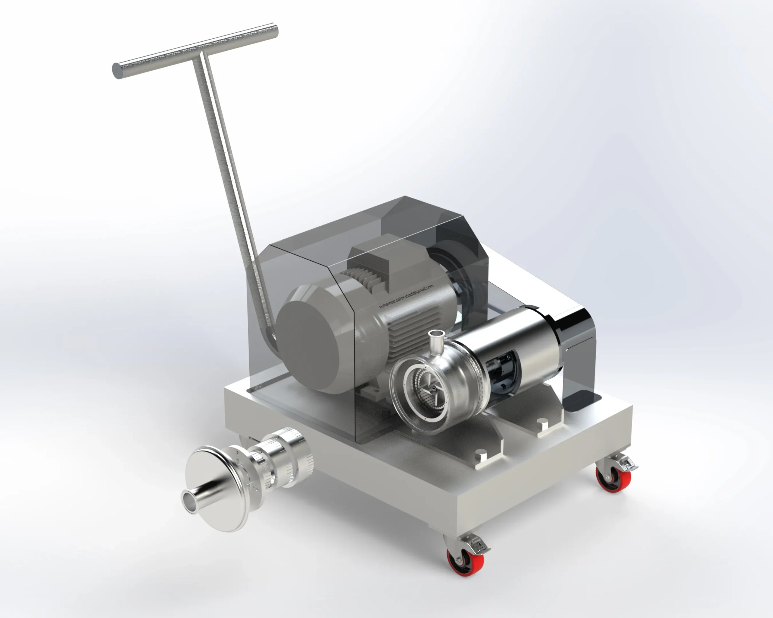
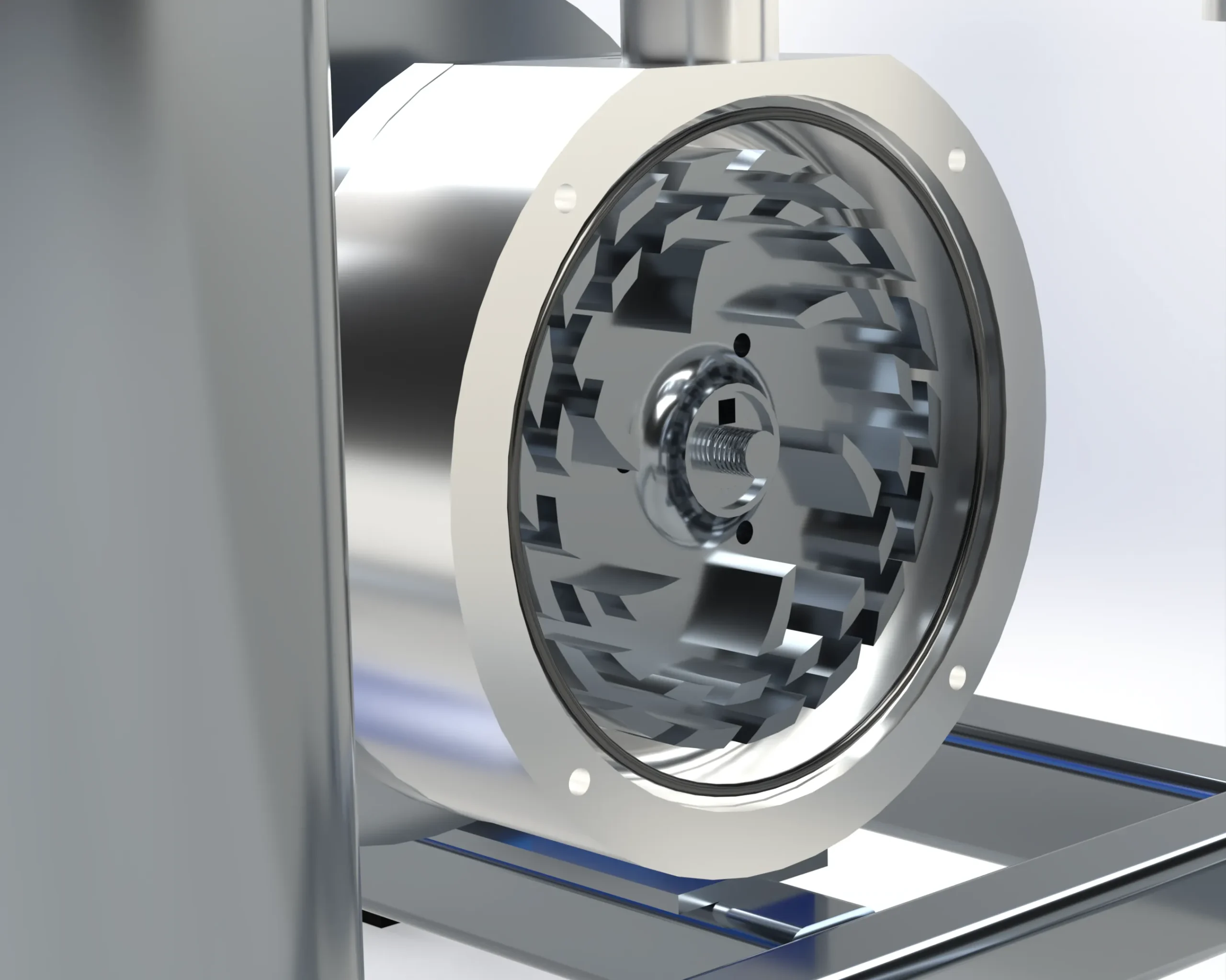
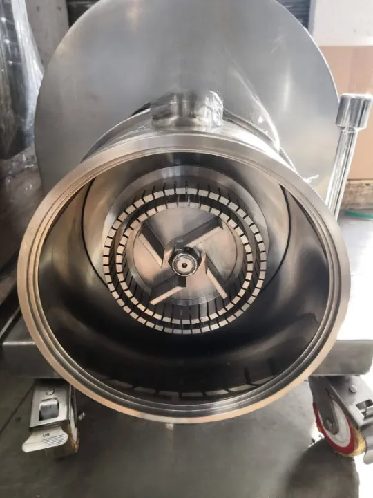
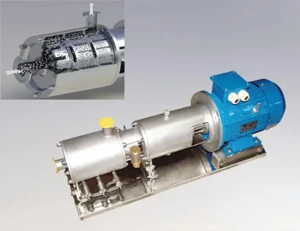
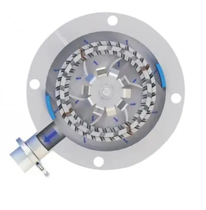
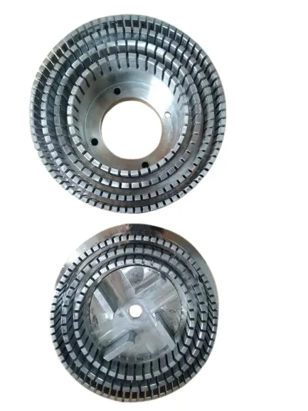
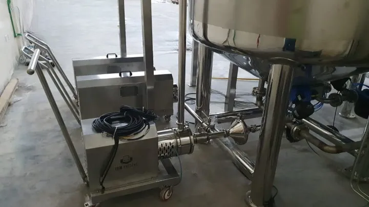
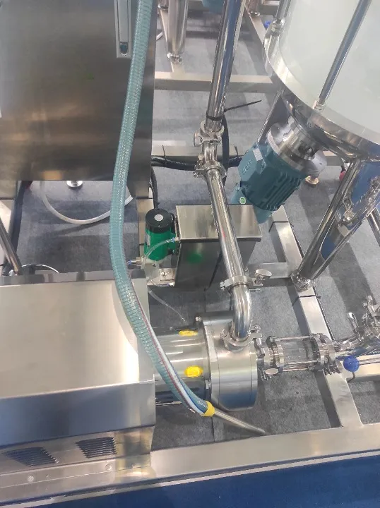
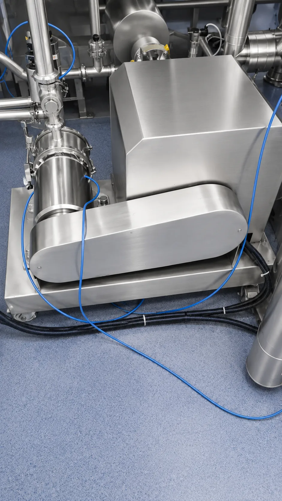
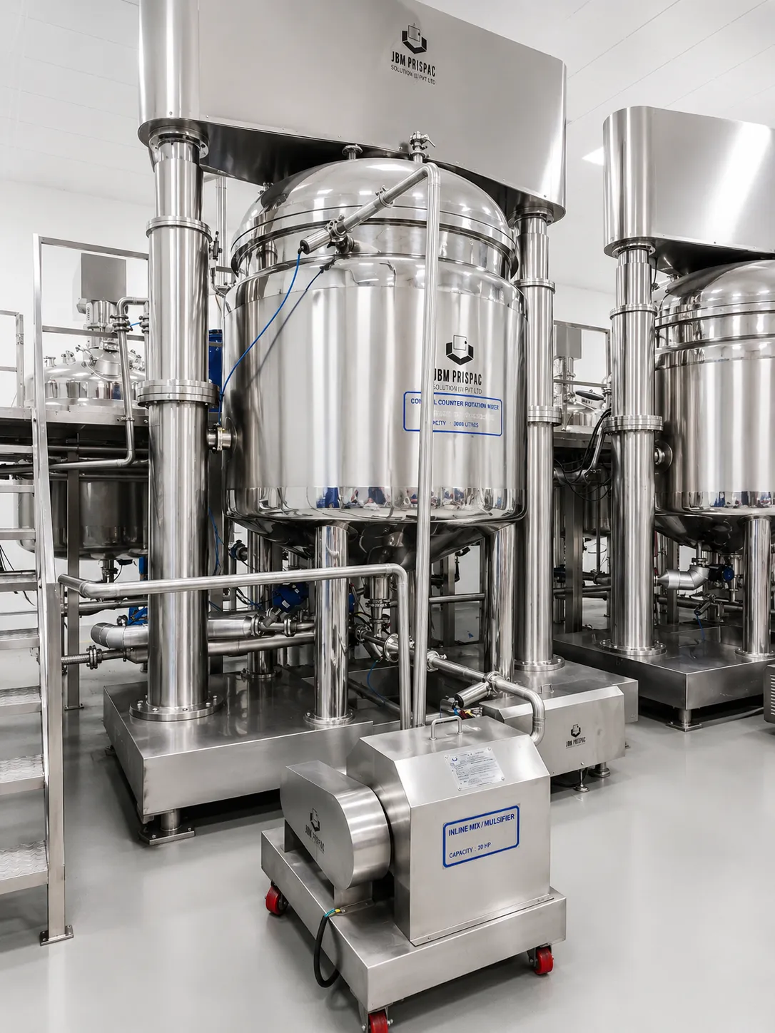
Product enters Stage 1 where the first rotor–stator gap delivers initial shear breaking large agglomerates; each successive stage applies progressively finer gap clearance and higher localised shear — reducing droplets step-by-step to <1–5 µm. The cascade design achieves in a single pass what multiple recirculation loops accomplish in single-stage systems. Stage count (2–4) and gap geometry are configured at order for the specific application. The multi-stage workhead maintains the no-bypass design — 100% of product processes through every stage every pass, guaranteeing uniform particle size distribution.
Challenges
Higher Pressure Drop Across Multiple Stages (0.5–3 bar)
Cumulative stage resistance requires stronger self-pumping or dedicated external feed pump.
Cumulative Heat Generation Across All Stages (10–25°C Rise)
Each successive stage adds shear energy — total temperature rise exceeds single-stage by 2–4×.
Complex Multi-Stage Workhead CIP Validation
Multiple gap surfaces require validated CIP spray coverage at every stage without workhead disassembly.
Stage Matching to Product Viscosity Profile
As product viscosity changes during concentration, optimal stage gaps may shift from design point.
Higher Capital Cost vs. Single-Stage
Multi-stage machined workhead and precision gap control commands 1.5–2.5× single-stage price.
Solutions
- Progressive Coarse-to-Fine Stage Gap Sequence: Stage 1: 0.3–0.5 mm → Stage 4: 0.05–0.15 mm — optimises energy distribution per stage.
- Inter-Stage Jacketed Cooling Zone: Cooling water jacket between each stage pair limits cumulative temperature rise to <5°C total.
- Modular Stage Cartridge (Individual Stage Removal Without Full Disassembly): Each stage cartridge extracts independently — CIP access and maintenance time reduced by 60%.
- VFD with Stage-Specific Power Monitoring: Per-stage power draw monitored in real time — detects wear or blockage before product impact.
- Pilot-Scale Multi-Stage Trial for Stage Count and Gap Optimisation: 2-stage pilot trial with inline PSD measurement validates stage selection before production order.
Applications
- Pharmaceutical: API nanosuspensions, sterile emulsions, parenteral fat emulsions — single-pass <1–5 µm.
- Food & Beverage: Mayonnaise, dairy cream, homogenised milk, beverage emulsions — high volume continuous.
- Cosmetics: Nanoemulsion serums, SPF lotions, hair conditioners — fine particle size in one pass.
- Chemical: Polymer emulsions, pigment nano-dispersions, adhesive fine dispersions.
- Nutraceuticals: Bioavailability-enhanced nano-emulsified supplements and functional beverage bases.
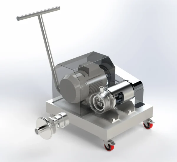
Models & Capacities
Type 2 — Multi-Stage Inline Rotor-Stator Homogeniser (2–4 Stages, Lab to Large Production) | ||||||||||||
Stages (R-S heads) | Flow Rate [L/h] | Rotor Speed [RPM] | Tip Speed [m/s] | D90 [µm] | Droplet D50 [µm] | Motor [kW] | Inlet/Outlet Ø [mm] | Op. Temp [°C] | Overall L×W×H [mm] | Weight [kg] |
| |
2 | 20–200 | 3,000–12,000 VFD | 5–23 | 0.2–20 | 0.1–10 | 0.55 | DN 10 | 2–95 | 310×165×220 | 14 |
| |
2 | 200–5,000 | 1,500–8,000 VFD | 8–25 | 0.2–20 | 0.1–10 | 1.5 | DN 32 | 2–95 | 480×245×310 | 52 |
| |
3 | 200–3,000 | 1,500–7,200 VFD | 8–25 | 0.1–15 | 0.05–5 | 2.2 | DN 32 | 2–95 | 560×280×350 | 78 |
| |
2 | 3,000–30,000 | 800–5,000 VFD | 10–25 | 0.2–20 | 0.1–10 | 7.5 | DN 65 | 2–95 | 720×385×460 | 185 |
| |
3 | 2,000–20,000 | 800–4,500 VFD | 10–25 | 0.1–15 | 0.05–5 | 11 | DN 65 | 2–95 | 850×420×510 | 265 |
| |
4 | 1,000–12,000 | 800–4,000 VFD | 10–25 | 0.05–8 | 0.02–3 | 15 | DN 65 | 2–95 | 980×480×580 | 360 |
| |
2 | 20,000–150,000 | 400–3,000 VFD | 10–22 | 0.2–20 | 0.1–10 | 37 | DN 150 | 2–95 | 1,220×680×800 | 720 |
| |
3 | 10,000–100,000 | 400–2,500 VFD | 10–22 | 0.1–15 | 0.05–5 | 55 | DN 150 | 2–95 | 1,400×750×880 | 1,050 |
| |
4 | 5,000–60,000 | 400–2,000 VFD | 10–22 | 0.05–8 | 0.02–3 | 75 | DN 150 | 2–95 | 1,600×820×960 | 1,450 |
| |