
Vacuum Plough Shear Mixer-Dryer (Integrated Granulation + Drying)
A vacuum plough shear mixer-dryer integrates the wet granulation capability of a plough shear mixer with a jacketed vessel (40–150°C) and vacuum system (−0.85 to −0.98 bar) — enabling wet granulation followed immediately by in-situ vacuum drying in the same vessel without product transfer. Processing 10–2,000 L batches from LOD 25–40% wet mass to LOD <2% dried granule in 60–180 minutes total cycle time, it eliminates the FBP drying step and associated transfer losses — reducing granulation-to-drying cycle time by 40–60%.
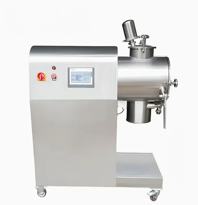
A vacuum plough shear mixer-dryer integrates the wet granulation capability of a plough shear mixer with a jacketed vessel (40–150°C) and vacuum system (−0.85 to −0.98 bar) — enabling wet granulation followed immediately by in-situ vacuum drying in the same vessel without product transfer. Processing 10–2,000 L batches from LOD 25–40% wet mass to LOD <2% dried granule in 60–180 minutes total cycle time, it eliminates the FBP drying step and associated transfer losses — reducing granulation-to-drying cycle time by 40–60%.
Wet granulation proceeds with plough blades at 60–250 RPM and binder addition through top nozzles. At granulation endpoint, the vacuum system engages (−0.85 to −0.98 bar) and the jacket temperature rises to 40–90°C — evaporating solvent and moisture from the moving granule bed. Blade speed reduces to 5–30 RPM for gentle drying agitation — continuously turning granules to expose fresh surface to the vacuum-drying zone. Vapour exits through the top vacuum outlet to a condenser and solvent recovery system. LOD is monitored in real time by a calibrated NIR probe mounted in the vessel wall.
Challenges
Granule Attrition During Vacuum Drying at Blade Speed
Even 5–30 RPM blade rotation during drying progressively abrades partially dried granules.
Vacuum Seal Integrity at Rotating Plough Shaft
Shaft seal under −0.9 bar with granule particles present accelerates seal wear — vacuum loss.
Drying Non-Uniformity in Large-Diameter Vessels
Radial temperature gradient from jacket wall to vessel centre creates uneven LOD across granule bed.
Solvent Recovery Condenser Sizing for Rapid Evaporation Rate
Initial high evaporation rate from wet granule exceeds condenser capacity — vacuum breaks.
CIP Validation for Combined Granulation + Drying Vessel Geometry
Combined process vessel with nozzles, baffles, and vacuum ports requires full CIP spray coverage.
Solutions
- VFD Blade Speed Reduction to 5–15 RPM During Drying Phase: Low-speed gentle agitation limits granule attrition to <2% during vacuum drying phase.
- Double Mechanical Seal with Barrier Fluid (−0.95 bar Rated): Pressurised barrier fluid maintains seal face lubrication under full vacuum — zero vacuum loss.
- Internal Heating Element (Distributed Heating Array) for Large Vessels: Supplementary internal heating panel eliminates radial gradient — uniform LOD across full vessel.
- Staged Vacuum Pull-Down (−0.3 → −0.6 → −0.9 bar in Three Steps): Gradual vacuum increase matches evaporation rate to condenser capacity — steady drying.
- Full CIP Spray Ball + Vacuum Port Flush + Nozzle Purge Sequence: CIP protocol covers all internal surfaces; vacuum port and nozzle flush cycles validated by TOC wipe.
Applications
- Pharmaceutical: Single-vessel granulation + drying for heat-sensitive API — eliminates transfer exposure and product loss.
- Nutraceuticals: Vitamin and herbal supplement single-vessel processing — short cycle; low degradation.
- Chemical: Specialty chemical granule formation and drying in one closed vessel — solvent recovery validated.
- Cosmetics: Active cosmetic ingredient granule preparation and drying without inter-step handling.
- Biotechnology: Biological active powder granule preparation requiring closed processing from wet to dry.
Models & Capacities
1B — High-Shear Plough Shear Mixer with Choppers (PSW-HC) — 10 L Lab to 3,000 L Large Production — Dual Shear Zones — Granule D90 0.1–1.0 mm | ||||||||||
Model | Scale | Bowl Vol [L] | Batch Size [kg] | Blade Motor [kW] | Chopper Count | Chopper Motor [kW ea.] | Chopper RPM | Granule D90 [mm] | L × W × H [mm] | Weight [kg] |
PSW-HC-010 | Lab | 10 | 2 – 6 | 1.5 – 3 | 1 | 0.37 | 1,500 – 3,000 | 0.1 – 1.0 | 950 × 600 × 1,200 | 320 |
PSW-HC-030 | Pilot | 30 | 8 – 18 | 4 – 7.5 | 2 | 0.55 – 0.75 | 1,500 – 3,000 | 0.1 – 1.0 | 1,300 × 800 × 1,500 | 620 |
PSW-HC-100 | Pilot/Prod | 100 | 30 – 60 | 11 – 18.5 | 2 | 1.1 – 1.5 | 1,500 – 3,000 | 0.1 – 1.0 | 1,800 × 1,050 × 1,850 | 1,250 |
PSW-HC-300 | Production | 300 | 90 – 180 | 30 – 37 | 3 | 1.5 – 2.2 | 1,500 – 3,000 | 0.1 – 1.0 | 2,650 × 1,350 × 2,200 | 2,600 |
PSW-HC-600 | Production | 600 | 180 – 360 | 55 – 75 | 3 | 2.2 – 3.0 | 1,500 – 3,000 | 0.1 – 1.0 | 3,400 × 1,700 × 2,600 | 5,000 |
PSW-HC-1000 | Large Prod | 1,000 | 300 – 600 | 90 – 132 | 4 | 3.0 – 4.0 | 1,500 – 3,000 | 0.1 – 1.0 | 4,200 × 2,000 × 3,000 | 8,800 |
PSW-HC-3000 | Large Prod | 3,000 | 900 – 1,800 | 220 – 280 | 4 | 5.5 – 7.5 | 1,500 – 2,500 | 0.1 – 1.0 | 7,200 × 2,900 × 3,600 | 21,000 |